Toyota 4Runner: Hydraulic Test
HYDRAULIC TEST
1. PERFORM HYDRAULIC TEST
(a) Measure the line pressure.
CAUTION:
The line pressure test should always be carried out in pairs. One technician should observe the conditions of the wheels and wheel stoppers from outside the vehicle while the other is performing the test.
NOTICE:
- Perform the test while the ATF (Automatic Transmission Fluid) temperature is 50 to 80°C (122 to 176°F).
- Be careful to prevent SST hose from interfering with the exhaust pipe.
- This check must be conducted after checking and adjusting the engine.
- Perform the test with the A/C off.
- When conducting the stall test, do not continue for more than 5 seconds.
- When performing the stall speed test more than once, make sure to wait 15 seconds or more between tests.
(1) Warm up the ATF (Automatic Transmission Fluid).
(2) Turn the ignition switch off.
(3) Lift the vehicle up.
(4) Remove the test plug from the transmission case and connect SST.
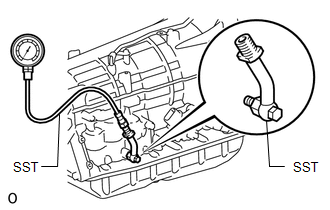
SST: 09992-00095
09992-00231
09992-00271
(5) Lower the vehicle.
(6) Fully apply the parking brake and chock the 4 wheels.
(7) Start the engine and check the idling speed.
(8) Keep your left foot pressed firmly on the brake pedal and move the shift lever to D.
(9) Measure the line pressure when the engine is idling.
(10) Fully depress the accelerator pedal with your right foot. Quickly read the highest line pressure when the engine speed reaches stall speed.
(11) In the same manner, perform the test with the shift lever in R.
Specified Line Pressure|
Condition |
D Position |
R Position |
|---|---|---|
|
Stall test |
1200 to 1450 kPa (12.2 to 14.8 kgf/cm2, 174 to 210 psi) |
1150 to 1400 kPa (11.7 to 14.3 kgf/cm2, 167 to 203 psi) |
|
Problem |
Possible Cause |
|---|---|
|
Measured values at all positions are higher than specified pressure |
|
|
Measured values at all positions are lower than specified pressure |
|
|
Pressure is low in D only |
|
|
Pressure is low in R only |
|
 Mechanical System Tests
MECHANICAL SYSTEM TESTS
1. STALL SPEED TEST
HINT:
This test is to check the overall performance of the engine and transmission.
CAUTION:
To ensure safety, perform this test in an open and ...
 Manual Shifting Test
MANUAL SHIFTING TEST
1. MANUAL SHIFTING TEST
HINT:
Through this test, it can be determined whether the trouble occurs in
an electrical circuit or if it is a mechanical problem in the tr ...
Other materials about Toyota 4Runner:
Installation
INSTALLATION
PROCEDURE
1. INSTALL CENTER CONTROL ABSORBER BRACKET LH
(a) Install the center control absorber bracket with the 2 bolts.
Torque:
29 N·m {296 kgf·cm, 21 ft·lbf}
2. INSTALL CENTER CONTROL ABSORBER BRACKET RH
HINT:
Use the same procedure ...
Sleep Operation Failure of Occupant Classification ECU (B1796)
DESCRIPTION
During sleep mode, the occupant classification ECU monitors the condition of
each sensor while the ignition switch is off. In this mode, if the occupant classification
ECU detects an internal malfunction, DTC B1796 is stored.
DTC C ...

0.0108