Toyota 4Runner: IG Power Source Circuit
DESCRIPTION
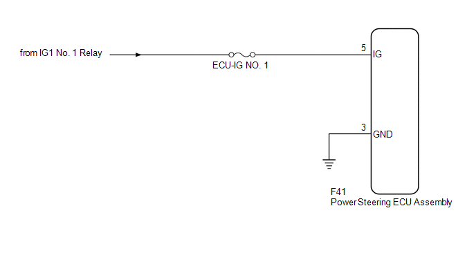
When the ignition switch is turned to ON, the IG power source circuit supplies positive (+) voltage to the power steering ECU assembly.
WIRING DIAGRAM
CAUTION / NOTICE / HINT
NOTICE:
Inspect the fuses for circuits related to this system before performing the following inspection procedure.
PROCEDURE
|
1. |
CHECK HARNESS AND CONNECTOR (POWER STEERING ECU ASSEMBLY - BATTERY AND BODY GROUND) |
.gif)
| OK | .gif) |
PROCEED TO NEXT SUSPECTED AREA SHOWN IN PROBLEM SYMPTOMS TABLE |
| NG | |
REPAIR OR REPLACE HARNESS OR CONNECTOR |
 Power Steering Warning Light Circuit
DESCRIPTION
The power steering ECU assembly is connected to the combination meter assembly
via CAN communication. If the power steering ECU assembly detects a malfunction,
the power steering warn ...
 Vane Pump
...
Other materials about Toyota 4Runner:
Speed Sensor Circuit Malfunction (C1883/83)
DESCRIPTION
The stabilizer control ECU receives the speed signal from the skid control ECU
via CAN communication.
DTC Code
DTC Detection Condition
Trouble Area
C1883/83
The stabilizer control ECU ...
Removal
REMOVAL
PROCEDURE
1. REMOVE DOOR SCUFF PLATE ASSEMBLY LH
2. REMOVE COWL SIDE TRIM BOARD LH
3. REMOVE NO. 2 SWITCH HOLE BASE
4. REMOVE NO. 1 INSTRUMENT CLUSTER FINISH PANEL GARNISH
5. REMOVE LOWER INSTRUMENT PANEL FINISH PANEL SUB-ASSEMBLY
...

0.0066