Toyota 4Runner: Illumination for Panel Switch does not Come on with Tail Switch ON
CAUTION / NOTICE / HINT
NOTICE:
After replacing the navigation receiver assembly of vehicles subscribed to pay-type satellite radio broadcasts, registration of the XM radio ID is necessary.
PROCEDURE
|
1. |
CHECK VEHICLE SIGNAL (OPERATION CHECK) |
(a) Enter the "Vehicle Signal Check Mode" screen. Refer to Check Vehicle Signal
in Operation Check (See page .gif) ).
).
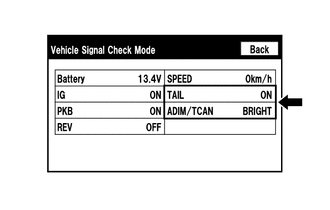
(b) Check that the display for "TAIL" changes between ON and OFF according to the light control switch operation.
OK:
|
Light Control Switch |
Display |
|---|---|
|
Tail or head |
ON |
|
Off |
OFF |
HINT:
This display is updated once per second. As a result, it is normal for the display to lag behind the actual switch operation.
(c) Check that the display for "ADIM/TCAN" changes between DIM and BRIGHT according to the light control switch operation.
OK:
|
Light Control Switch |
Display |
|---|---|
|
Tail or head |
DIM |
|
Off |
BRIGHT |
| OK | .gif) |
REPLACE NAVIGATION RECEIVER ASSEMBLY |
| NG | |
PROCEED TO NEXT SUSPECTED AREA SHOWN IN PROBLEM SYMPTOMS TABLE |
 Radio Broadcast cannot be Received or Poor Reception
CAUTION / NOTICE / HINT
NOTICE:
After replacing the navigation receiver assembly of vehicles subscribed to pay-type
satellite radio broadcasts, XM radio ID registration is necessary.
PROCEDURE
...
 Display does not Dim when Light Control Switch is Turned ON
CAUTION / NOTICE / HINT
NOTICE:
After replacing the navigation receiver assembly of vehicles subscribed to pay-type
satellite radio broadcasts, registration of the XM radio ID is necessary.
PROCE ...
Other materials about Toyota 4Runner:
Sending Malfunction (Navigation to APGS) (U0073,U0140)
DESCRIPTION
These DTCs are stored when a malfunction occurs in the CAN communication circuit.
DTC No.
DTC Detection Condition
Trouble Area
U0073
CAN bus connection error
CAN communicatio ...
Moon roof
Use the overhead switches to open and close the moon roof and tilt it up
and down.
Opening and closing
1. Opens the moon roof* The moon roof stops slightly before the fully open
position to reduce wind noise.
Press the switch again to fully open the m ...

0.0085