Toyota 4Runner: Inner Rear View Mirror
Components
COMPONENTS
ILLUSTRATION
.png)
Inspection
INSPECTION
PROCEDURE
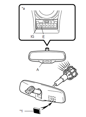
1. INSPECT INNER REAR VIEW MIRROR ASSEMBLY (w/ EC Mirror)
(a) Check operation of the electrochromic mirror.
 Text in Illustration
|
*1 |
Black-colored Tape |
|
*a |
Component without harness connected (Inner Rear View Mirror Assembly) |
|
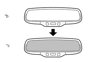
*b |
Bright |
|
*c |
Dark |
(1) Connect the positive (+) lead of the battery to terminal 7 (IG) and the negative (-) lead to terminal 6 (E).
(2) Check that the LED labeled A in the illustration is illuminated.
(3) Attach black-colored tape to the forward sensor to prevent it from sensing light.
(4) Shine an electric light on the mirror. Check that the mirror surface changes from bright to dark.
HINT:
When the environment is very bright, the antiglare operation may occur immediately after the tape is applied.
If the result is not as specified, replace the inner rear view mirror assembly.
Installation
INSTALLATION
PROCEDURE
1. INSTALL INNER REAR VIEW MIRROR ASSEMBLY (w/ EC Mirror)
(a) Using a T20 "TORX" socket wrench, install the inner rear view mirror assembly with the screw.
Torque:
1.5 N·m {15 kgf·cm, 13 in·lbf}
(b) Connect the connector.
2. INSTALL INNER REAR VIEW MIRROR STAY HOLDER COVER (w/ EC Mirror)
|
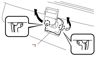
(a) Attach the 2 claws to install the inner rear view mirror stay holder cover. |
|
|
(b) Attach the 2 guides to install the inner rear view mirror stay holder cover as shown in the illustration. |
|
3. INSTALL INNER REAR VIEW MIRROR ASSEMBLY (w/o EC Mirror)
|
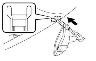
(a) Slide and install the inner rear view mirror assembly as shown in the illustration. |
|
|
(b) Attach the 2 claws to install the cover. |
|
Removal
REMOVAL
PROCEDURE
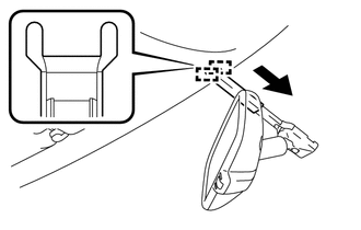
1. REMOVE INNER REAR VIEW MIRROR ASSEMBLY (w/o EC Mirror)
(a) Pinch the cover and detach the 2 claws. Then remove the cover.
Text in Illustration|
*1 |
Cover |
|
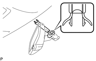
(b) Pull the lever, and then slide to remove the inner rear view mirror assembly. Text in Illustration
|
|
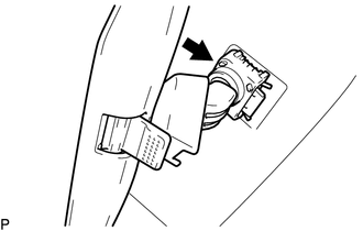
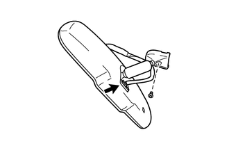
2. REMOVE INNER REAR VIEW MIRROR STAY HOLDER COVER (w/ EC Mirror)
|
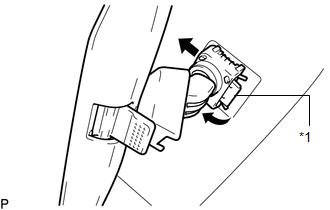
(a) Detach the 2 guides to slide the inner rear view mirror stay holder cover in the direction indicated by the arrow in the illustration. |
|
|
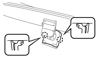
(b) Detach the 2 claws to remove the inner rear view mirror stay holder cover. |
|
.png)
3. REMOVE INNER REAR VIEW MIRROR ASSEMBLY (w/ EC Mirror)
(a) Disconnect the connector.
(b) Using a T20 "TORX" socket wrench, remove the screw and inner rear view mirror assembly.
 Mirror (int)
...

Other materials about Toyota 4Runner:
Installation
INSTALLATION
PROCEDURE
1. INSTALL VOLTAGE INVERTER ASSEMBLY
(a) Install the voltage inverter with the 3 bolts.
Torque:
7.5 N·m {76 kgf·cm, 66 in·lbf}
(b) Connect the 2 connectors.
2. INSTALL DECK TRIM SIDE PANEL ASSEMBLY RH
3. INSTALL FRONT DECK ...
Reassembly
REASSEMBLY
PROCEDURE
1. INSTALL REAR PROPELLER SHAFT UNIVERSAL JOINT SPIDER BEARING
HINT:
Use the same procedure for all rear propeller shaft universal joint spider bearing.
(a) Apply MP grease No. 2 to a new spider and bearings.
NOTICE:
...

0.0262