Toyota 4Runner: Removal
REMOVAL
PROCEDURE
1. DISCONNECT CABLE FROM NEGATIVE BATTERY TERMINAL
CAUTION:
Wait at least 90 seconds after disconnecting the cable from the negative (-) battery terminal to disable the SRS system.
NOTICE:
When disconnecting the cable, some systems need to be initialized after the cable
is reconnected (See page .gif) ).
).
2. REMOVE DOOR SCUFF PLATE ASSEMBLY RH
3. REMOVE COWL SIDE TRIM BOARD RH
4. REMOVE NO. 2 INSTRUMENT CLUSTER FINISH PANEL GARNISH
5. REMOVE NO. 2 INSTRUMENT PANEL UNDER COVER SUB-ASSEMBLY
6. REMOVE INSTRUMENT LOWER COVER LH
7. REMOVE INSTRUMENT NO. 2 LOWER PANEL AIRBAG ASSEMBLY
8. REMOVE INSTRUMENT PANEL BOX DOOR COVER
9. REMOVE INSTRUMENT LOWER PANEL SUB-ASSEMBLY
10. REMOVE NO. 2 AIR DUCT SUB-ASSEMBLY
11. REMOVE ECU INTEGRATION BOX RH
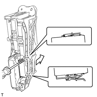
12. REMOVE POWER STEERING ECU ASSEMBLY
|
(a) Using a screwdriver, detach the 2 claws and remove the power steering ECU assembly. HINT: Tape the screwdriver tip before use. |
|
 Components
COMPONENTS
ILLUSTRATION
...
 Installation
INSTALLATION
CAUTION / NOTICE / HINT
HINT:
A bolt without a torque specification is shown in the standard bolt chart (See
page ).
PROCEDURE
1. INSTALL POWER STEERING ECU ASSEMBLY
(a) Attach t ...
Other materials about Toyota 4Runner:
Removal
REMOVAL
PROCEDURE
1. REMOVE NO. 1 ENGINE UNDER COVER SUB-ASSEMBLY
2. REMOVE REAR ENGINE UNDER COVER ASSEMBLY
3. REMOVE FRONT FENDER APRON SEAL RH
4. REMOVE FRONT NO. 1 FENDER APRON TO FRAME SEAL RH
5. REMOVE NO. 1 OIL COOLER INLET HOSE AND NO ...
Diagnostic Trouble Code Chart
DIAGNOSTIC TROUBLE CODE CHART
HINT:
If a trouble code is output during the DTC check, inspect the trouble areas listed
for that code. For details of the code, refer to the "See page" below.
Wireless Door Lock Control System
DTC Code
...

0.0265