Toyota 4Runner: Inspection
INSPECTION
PROCEDURE
1. INSPECT GENERATOR WITH CLUTCH PULLEY
(a) Hold the center of the generator with clutch pulley and check that the outer ring turns counterclockwise and does not turn clockwise.
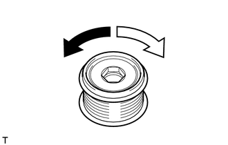 Text in Illustration
.png) |
Free |
.png) |
Lock |
If the result is not as specified, replace the generator with clutch pulley.
2. INSPECT GENERATOR BRUSH HOLDER ASSEMBLY
|
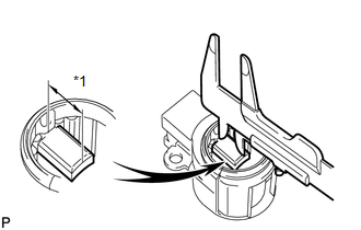
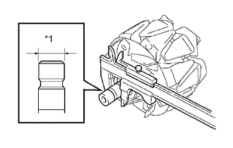
(a) Using a vernier caliper, measure the brush length. Standard exposed length: 9.5 to 11.5 mm (0.374 to 0.453 in.) Minimum exposed length: 4.5 mm (0.177 in.) Text in Illustration
If the brush length is less than the minimum, replace the generator brush holder assembly. |
|
3. INSPECT GENERATOR ROTOR ASSEMBLY
|
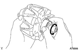
(a) Check that the generator rotor bearing is not rough or worn. If necessary, replace the generator rotor assembly. |
|
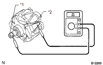
(b) Check the generator rotor for an open circuit.
|
(1) Measure the resistance according to the value(s) in the table below. Standard Resistance:
If the result is not as specified, replace the generator rotor assembly. |
|
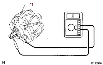
(c) Check if the generator rotor is grounded.
|
(1) Measure the resistance according to the value(s) in the table below. Standard Resistance:
If the result is not as specified, replace the generator rotor assembly. |
|
|
(d) Using a vernier caliper, measure the slip ring diameter. Standard diameter: 14.2 to 14.4 mm (0.559 to 0.567 in.) Minimum diameter: 14.0 mm (0.551 in.) Text in Illustration
If the diameter is less than the minimum, replace the generator rotor assembly. |
|
 Disassembly
DISASSEMBLY
PROCEDURE
1. REMOVE GENERATOR PULLEY CAP
(a) Using a screwdriver, remove the generator pulley cap.
2. REMOVE GENERATOR WITH CLUTCH ...
 Reassembly
REASSEMBLY
PROCEDURE
1. INSTALL GENERATOR DRIVE END FRAME BEARING
(a) Using SST and a press, press in a new generator drive end frame bearing.
SST: 09950-60010
09951-00470
SST: ...
Other materials about Toyota 4Runner:
Disassembly
DISASSEMBLY
PROCEDURE
1. REMOVE SHIFT LEVER CAP
2. REMOVE POSITION INDICATOR HOUSING ASSEMBLY
(a) Detach the 4 claws and remove the floor shift position indicator
housing.
3. REMOVE INDICATOR LIGHT ...
Inspection
INSPECTION
PROCEDURE
1. INSPECT PROPELLER SHAFT ASSEMBLY
(a) Using a dial indicator, check the propeller shaft runout.
Maximum runout:
0.4 mm (0.0157 in.)
If the shaft runout is more than the maximum, replace the shaft.
...

0.019