Toyota 4Runner: Disassembly
DISASSEMBLY
PROCEDURE
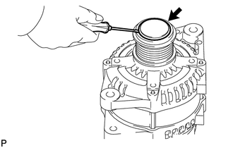
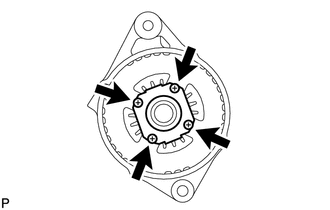
1. REMOVE GENERATOR PULLEY CAP
|
(a) Using a screwdriver, remove the generator pulley cap. |
|
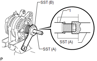
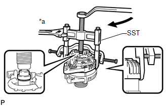
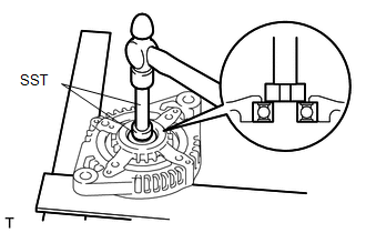
2. REMOVE GENERATOR WITH CLUTCH PULLEY
(a) Mount the generator in a vise between aluminum plates.
|
(b) Install SST (A) and SST (B) to the generator with clutch pulley as shown in the illustration. SST: 09820-63021 Text in Illustration
NOTICE: Securely attach SST to the generator with clutch pulley and generator rotor shaft. |
|
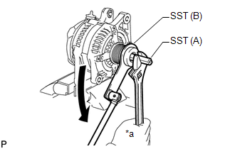
(c) Use a wrench to hold SST (A) and turn SST (B) counterclockwise to loosen the generator with clutch pulley.
 Text in Illustration
|
*a |
Hold |
.png) |
Turn |
NOTICE:
Be careful as the generator with clutch pulley or generator rotor shaft may be damaged if the position of SST is not securely maintained while performing this operation.
(d) Remove SST from the generator.
(e) Remove the generator with clutch pulley from the rotor shaft.
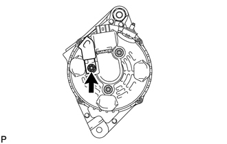
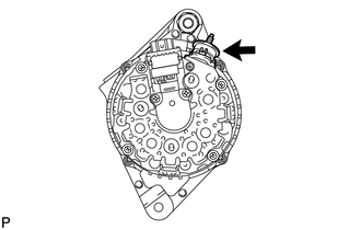
3. REMOVE GENERATOR REAR END COVER
|
(a) Remove the nut and cord clip. |
|
|
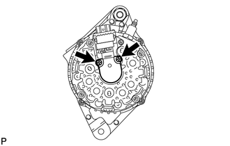
(b) Remove the 3 nuts and generator rear end cover. |
|
4. REMOVE TERMINAL INSULATOR
|
(a) Remove the terminal insulator from the generator coil. |
|
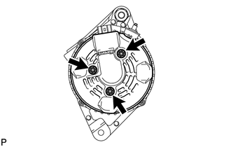
5. REMOVE GENERATOR BRUSH HOLDER ASSEMBLY
|
(a) Remove the 2 screws and brush holder from the generator coil. |
|
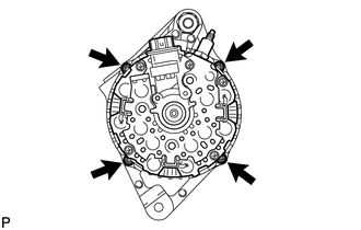
6. REMOVE GENERATOR COIL ASSEMBLY
|
(a) Remove the 4 bolts. |
|
(b) Using SST, remove the generator coil assembly.
SST: 09950-40011
09951-04020
09952-04010
09953-04020
09954-04010
09955-04071
09957-04010
09958-04011
Text in Illustration|
*a |
Hold |
|
|
Turn |
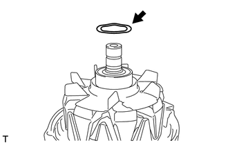
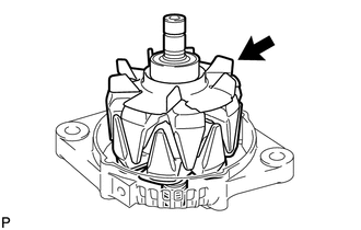
7. REMOVE GENERATOR ROTOR ASSEMBLY
|
(a) Remove the generator washer. |
|
|
(b) Remove the generator rotor assembly. |
|
8. INSPECT GENERATOR DRIVE END FRAME BEARING
|
(a) Check that the drive end frame bearing is not rough or worn. If necessary, replace the generator drive end frame bearing. |
|
9. REMOVE GENERATOR DRIVE END FRAME BEARING
|
(a) Remove the 4 screws and retainer plate from the drive end frame. |
|
|
(b) Using SST and a hammer, tap out the drive end frame bearing from the drive end frame. SST: 09950-60010 09951-00250 SST: 09950-70010 09951-07100 |
|
 Removal
REMOVAL
PROCEDURE
1. DISCONNECT CABLE FROM NEGATIVE BATTERY TERMINAL
NOTICE:
When disconnecting the cable, some systems need to be initialized after the cable
is reconnected (See page ).
2. DI ...
 Inspection
INSPECTION
PROCEDURE
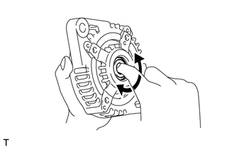
1. INSPECT GENERATOR WITH CLUTCH PULLEY
(a) Hold the center of the generator with clutch pulley and check that the outer
ring turns counterclockwise and does not turn clockwi ...
Other materials about Toyota 4Runner:
Driver Side Solar Sensor Short Circuit (B14A2)
DESCRIPTION
The automatic light control sensor (solar sensor), which is installed on the
upper side of the instrument panel, detects sunlight and controls the air conditioning
in auto mode. The output current from the automatic light control sensor (sol ...
Floor mat
Use only floor mats designed specifically for vehicles of the same model
and model year as your vehicle. Fix them securely in place onto the carpet.
Insert the retaining hooks (clips) into the floor mat eyelets.
Turn the upper knob of each retaining ho ...

0.0258