Toyota 4Runner: Installation
INSTALLATION
CAUTION / NOTICE / HINT
HINT:
When installing the symbol emblem, No. 1 back door emblem and No. 1 roof side mark, heat the vehicle body, symbol emblem, No. 1 back door emblem and No. 1 roof side mark using a heat light.
Standard:
|
Item |
Temperature |
|---|---|
|
Vehicle Body |
40 to 60°C (104 to 140°F) |
|
Symbol Emblem |
20 to 30°C (68 to 86°F) |
|
No. 1 Back Door Emblem |
20 to 30°C (68 to 86°F) |
|
No. 1 Roof Side Mark |
20 to 30°C (68 to 86°F) |
NOTICE:
Do not heat the vehicle body, symbol emblem, No. 1 back door emblem or No. 1 roof side mark excessively.
PROCEDURE
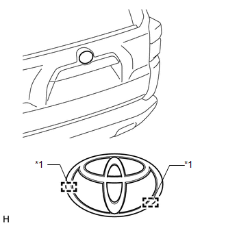
1. INSTALL SYMBOL EMBLEM
(a) Clean the vehicle body surface.
(1) Using a heat light, heat the vehicle body surface.
(2) Remove the double-sided tape from the vehicle body.
(3) Wipe off any tape adhesive residue with cleaner.
|
(b) Install a new symbol emblem. (1) Using a heat light, heat the vehicle body and a new symbol emblem. (2) Remove the peeling paper from the face of the symbol emblem. HINT: After removing the peeling paper, keep the exposed adhesive free from foreign matter. (3) Align the boss positions to install the symbol emblem. HINT: Press the symbol emblem firmly to install it. Text in Illustration
|
|
2. INSTALL NO. 1 BACK DOOR EMBLEM
(a) Clean the vehicle body surface.
(1) Using a heat light, heat the vehicle body surface.
(2) Remove the double-sided tape from the vehicle body.
(3) Wipe off any tape adhesive residue with cleaner.
(b) Install a new No. 1 back door emblem.
(1) Using a heat light, heat the vehicle body and a new No. 1 back door emblem.
(2) Remove the peeling paper from the face of the No. 1 back door emblem.
HINT:
After removing the peeling paper, keep the exposed adhesive free from foreign matter.
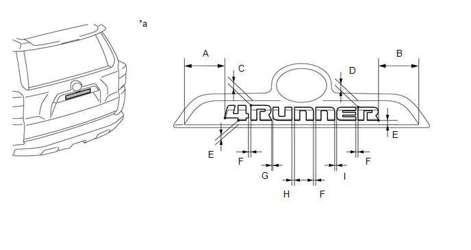
(3) Install the No. 1 back door emblem in the position shown in the installation.
 Text in Illustration
|
*a |
Reference Value |
- |
- |
Reference Measurement:
|
Area |
Measurement |
Area |
Measurement |
|---|---|---|---|
|
A |
105.0 mm (4.134 in.) |
B |
104.0 mm (4.094 in.) |
|
C |
11.8 mm (0.465 in.) |
D |
17.5 mm (0.689 in.) |
|
E |
10.5 mm (0.413 in.) |
F |
6.0 mm (0.236 in.) |
|
G |
4.0 mm (0.157 in.) |
H |
7.0 mm (0.276 in.) |
|
I |
5.5 mm (0.217 in.) |
- |
- |
3. INSTALL NO. 1 ROOF SIDE MARK
(a) Clean the vehicle body surface.
(1) Using a heat light, heat the vehicle body surface.
(2) Remove the double-sided tape from the vehicle body.
(3) Wipe off any tape adhesive residue with cleaner.
(b) Install a new No. 1 roof side mark.
(1) Using a heat light, heat the vehicle body and a new No. 1 roof side mark.
(2) Remove the peeling paper from the face of the No. 1 roof side mark.
HINT:
After removing the peeling paper, keep the exposed adhesive free from foreign matter.
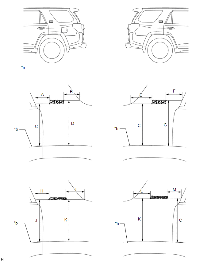
(3) Install the No. 1 roof side mark in the position shown in the installation.
 Text in Illustration
|
*a |
Reference Value |
*b |
Over Fender End Line |
Reference Measurement:
|
Area |
Measurement |
Area |
Measurement |
|---|---|---|---|
|
A |
95.0 mm (3.740 in.) |
B |
122.1 mm (4.807 in.) |
|
C |
346.6 mm (13.646 in.) |
D |
371.0 mm (14.606 in.) |
|
E |
157.3 mm (6.193 in.) |
F |
105.2 mm (4.142 in.) |
|
G |
370.9 mm (14.602 in.) |
H |
79.6 mm (3.134 in.) |
|
I |
149.4 mm (5.882 in.) |
J |
346.7 mm (13.650 in.) |
|
K |
346.9 mm (13.657 in.) |
L |
141.5 mm (5.571 in.) |
|
M |
87.7 mm (3.453 in.) |
- |
- |
 Components
COMPONENTS
ILLUSTRATION
ILLUSTRATION
...
 Removal
REMOVAL
CAUTION / NOTICE / HINT
HINT:
When removing the symbol emblem, No. 1 back door emblem and No. 1 roof side mark,
heat the vehicle body, symbol emblem, No. 1 back door emblem and No. 1 roof ...
Other materials about Toyota 4Runner:
Removal
REMOVAL
PROCEDURE
1. REMOVE FRONT WHEEL
2. REMOVE SIDE STEP ASSEMBLY LH
3. REMOVE STABILIZER CONTROL VALVE PROTECTOR
4. DRAIN SUSPENSION FLUID
5. REMOVE LOWER FRONT BUMPER COVER
6. REMOVE NO. 1 ENGINE UNDER COVER SUB-ASSEMBLY
7. REMOVE F ...
Theft Deterrent System Presence Detection (B279C)
DESCRIPTION
If an ECM that is incompatible with the engine immobiliser system is installed,
the ECM stores this DTC.
DTC Code
DTC Detection Condition
Trouble Area
B279C
An ECM for vehicles withou ...

0.0121