Toyota 4Runner: Installation
INSTALLATION
PROCEDURE
1. INSTALL AUTOMATIC LIGHT CONTROL SENSOR
|
(a) Attach the 2 claws to install the sensor. |
|
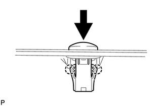
(b) Connect the connector.
2. INSTALL NO. 3 HEATER TO REGISTER DUCT
.gif)
3. INSTALL NO. 1 SIDE DEFROSTER NOZZLE DUCT
4. INSTALL NO. 2 SIDE DEFROSTER NOZZLE DUCT
5. INSTALL NO. 1 HEATER TO REGISTER DUCT
6. INSTALL NO. 2 HEATER TO REGISTER DUCT
7. INSTALL INSTRUMENT PANEL SUB-ASSEMBLY
(a) Install the instrument panel sub-assembly (See page
).
 Removal
REMOVAL
PROCEDURE
1. REMOVE INSTRUMENT PANEL SUB-ASSEMBLY
(a) Remove the instrument panel sub-assembly (See page
).
2. REMOVE NO. 1 HEATER TO REGISTER DUCT
3. REMOVE NO. 2 HEATER TO REGISTER ...

Other materials about Toyota 4Runner:
On-vehicle Inspection
ON-VEHICLE INSPECTION
PROCEDURE
1. INSPECT BRAKE PEDAL LOAD SENSING SWITCH
HINT:
Do not remove the brake pedal load sensing switch from the brake pedal
lever sub-assembly.
When there is a malfunction in the brake pedal load sensing switch, ...
On-vehicle Inspection
ON-VEHICLE INSPECTION
PROCEDURE
1. INSPECT VOLTAGE INVERTER ASSEMBLY
HINT:
Remove interior parts so that the voltage inverter can be seen.
(a) Disconnect the voltage inverter connector.
(b) Measur ...

0.0252