Toyota 4Runner: Removal
REMOVAL
PROCEDURE
1. REMOVE INSTRUMENT PANEL SUB-ASSEMBLY
(a) Remove the instrument panel sub-assembly (See page
.gif) ).
).
2. REMOVE NO. 1 HEATER TO REGISTER DUCT
3. REMOVE NO. 2 HEATER TO REGISTER DUCT
4. REMOVE NO. 1 SIDE DEFROSTER NOZZLE DUCT
5. REMOVE NO. 2 SIDE DEFROSTER NOZZLE DUCT
6. REMOVE NO. 3 HEATER TO REGISTER DUCT
7. REMOVE AUTOMATIC LIGHT CONTROL SENSOR
|
(a) Disconnect the connector. |
|
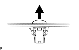
(b) Detach the 2 claws and remove the sensor.
 On-vehicle Inspection
ON-VEHICLE INSPECTION
PROCEDURE
1. CHECK AUTOMATIC LIGHT CONTROL SENSOR
(a) Measure the voltage according to the value(s) in the table below.
Standard Voltage:
Te ...
 Installation
INSTALLATION
PROCEDURE
1. INSTALL AUTOMATIC LIGHT CONTROL SENSOR
(a) Attach the 2 claws to install the sensor.
(b) Connect the connector.
2. I ...
Other materials about Toyota 4Runner:
Removal
REMOVAL
PROCEDURE
1. DISCONNECT CABLE FROM NEGATIVE BATTERY TERMINAL
NOTICE:
When disconnecting the cable, some systems need to be initialized after the cable
is reconnected (See page ).
2. REMOVE FRONT WHEELS
3. REMOVE NO. 1 ENGINE UNDER COVER SUB-AS ...
Diagnostic Trouble Code Chart
DIAGNOSTIC TROUBLE CODE CHART
HINT:
If a trouble code is output during the DTC check, inspect the trouble areas listed
for that code. For details of the code, refer to the "See page" below.
Power Window Control System
DTC Code
...

0.0263