Toyota 4Runner: Installation
INSTALLATION
PROCEDURE
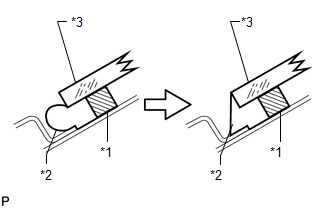
1. INSTALL NO. 1 WINDSHIELD GLASS STOPPER
|
(a) Install 2 new No. 1 windshield glass stoppers to the vehicle body as shown in the illustration. Text in Illustration
|
|
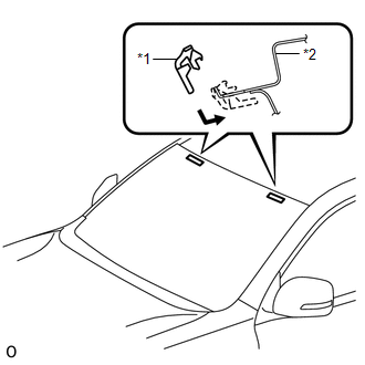
2. INSTALL NO. 2 WINDSHIELD GLASS STOPPER
(a) Apply Primer G to the windshield glass where the No. 2 windshield glass stoppers will be installed.
NOTICE:
- Allow the primer to dry for 3 minutes or more.
- Throw away any leftover primer.
- Do not apply too much primer.
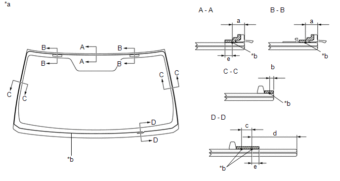
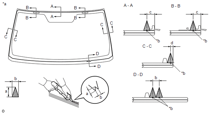
(b) Install 2 new No. 2 windshield glass stoppers to the windshield glass at the locations shown in the illustration.
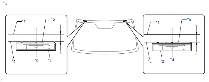 Text in Illustration
|
*1 |
Windshield Glass |
*2 |
No. 2 Windshield Glass Stopper |
|
*a |
Backside |
*b |
Ceramic Notch |
|
*c |
Ceramic Line |
d |
Center |
Standard:
|
Area |
Specified Condition |
|---|---|
|
a |
14.2 mm (0.559 in.) |
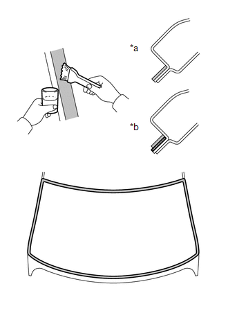
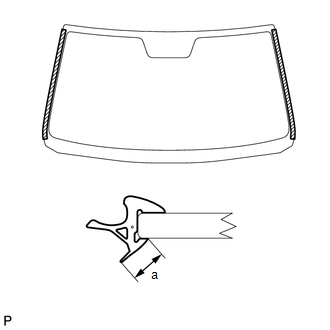
3. INSTALL WINDSHIELD OUTSIDE UPPER MOULDING
(a) Using a brush or sponge, coat the contact surface of the windshield glass and windshield outside upper moulding with Primer G as shown in the illustration.
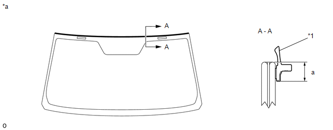 Text in Illustration
|
*1 |
Windshield Outside Upper Moulding |
- |
- |
|
*a |
Backside |
- |
- |
Standard:
|
Area |
Specified Condition |
|---|---|
|
a |
6.9 mm (0.272 in.) |
NOTICE:
- Allow the primer coating to dry for 3 minutes or more.
- Do not coat the adhesive with Primer G.
- Throw away any leftover primer.
(b) Remove the peeling paper from a new windshield outside upper moulding. Install the windshield outside upper moulding as shown in the illustration.
4. INSTALL WINDSHIELD GLASS ADHESIVE DAM
(a) Apply Primer G to the windshield glass where the windshield glass adhesive dam will be installed.
(b) Remove the peeling paper from the adhesive part of a new windshield glass adhesive dam. Install the windshield glass adhesive dam (adhesive side) to the windshield glass (Primer G area), but exclude the area above the notches on the upper part of the windshield glass.
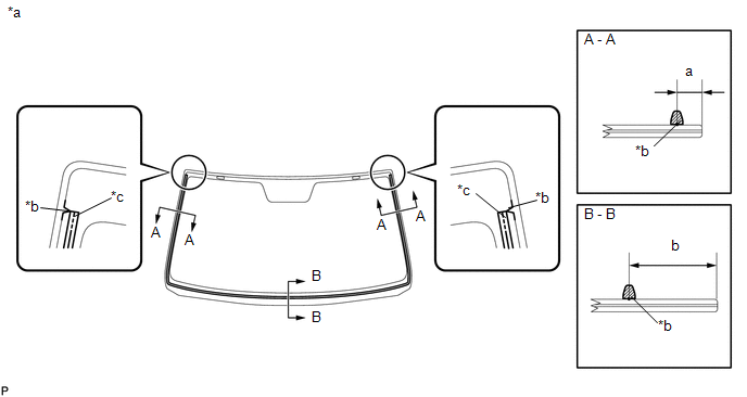 Text in Illustration
|
*a |
Backside |
*b |
Ceramic Notch |
|
*c |
Dam Center Line |
- |
- |
Standard:
|
Area |
Specified Condition |
|---|---|
|
a |
9.5 mm (0.374 in.) |
|
b |
37.7 mm (1.48 in.) |
NOTICE:
- Allow the primer to dry for 3 minutes or more.
- Throw away any leftover primer.
- Do not apply too much primer.
5. INSTALL WINDSHIELD GLASS
|
(a) Position the windshield glass. (1) Using suction cups, place the windshield glass in the correct position. (2) Check that the entire contact surface of the windshield glass rim is perfectly even. (3) Place matchmarks on the windshield glass and vehicle body at the locations indicated in the illustration. Text in Illustration
NOTICE: Check that the stoppers are attached to the vehicle body correctly. HINT:
(4) Using suction cups, remove the windshield glass. |
|
(b) Using a brush, apply Primer M to the exposed part of the vehicle body.
 Text in Illustration
|
*a |
CORRECT |
|
*b |
INCORRECT |
.png) |
Primer M |
.png) |
Adhesive |
NOTICE:
- Allow the primer to dry for 3 minutes or more.
- Do not apply primer to the adhesive.
- Throw away any leftover primer.
- Do not apply too much primer.
(c) Using a brush or sponge, apply Primer G to the contact surface of the windshield glass.
 Text in Illustration
|
*a |
Backside |
*b |
Adhesive Center Line |
|
|
Primer M |
- |
- |
Standard:
|
Area |
Specified Condition |
|---|---|
|
a |
9.5 mm (0.374 in.) |
|
b |
3.0 mm (0.118 in.) |
|
c |
8.0 mm (0.315 in.) |
|
d |
28.1 mm (1.11 in.) |
|
e |
7.0 mm (0.276 in.) |
NOTICE:
- Allow the primer to dry for 3 minutes or more.
- Throw away any leftover primer.
- Do not apply too much primer.
HINT:
If the primer is applied to an area that is not specified, apply non-residue solvent to a clean cloth and wipe off the excess primer before it dries.
(d) Apply adhesive to the windshield glass.
Adhesive:
Toyota Genuine Windshield Glass Adhesive or equivalent
(1) Cut off the tip of a cartridge nozzle as shown in the illustration.
HINT:
After cutting off the tip, use all adhesive within the time written in the table below.
Usage Time Frame:
|
Temperature |
Usage Time Frame |
|---|---|
|
35°C (95°F) |
15 minutes |
|
20°C (68°F) |
1 hour 40 minutes |
|
5°C (41°F) |
8 hours |
(2) Load a sealer gun with the cartridge.
(3) Apply adhesive to the windshield glass as shown in the illustration.
 Text in Illustration
|
*a |
Backside |
*b |
Adhesive Center Line |
|
|
Adhesive |
- |
- |
Standard:
|
Area |
Specified Condition |
|---|---|
|
a |
12.0 mm (0.472 in.) |
|
b |
8.0 mm (0.315 in.) |
|
c |
9.5 mm (0.374 in.) |
|
d |
3.0 mm (0.118 in.) |
(e) Install the windshield glass to the vehicle body.
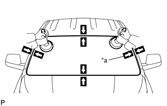
(1) Using suction cups, position the windshield glass so that the matchmarks are aligned. Press it in gently along the rim.
Text in Illustration|
*a |
Matchmark |
(2) Lightly press the outer surface of the windshield glass to ensure that it is securely fit to the vehicle body.
NOTICE:
- Check that the windshield glass stoppers are attached to the vehicle body correctly.
- Check that the vehicle body and windshield glass have a small gap between them.
|
(3) If necessary, use a scraper to correct the level or position of adhesive that has been applied. Text in Illustration
HINT: Apply adhesive to any areas where the amount of adhesive is inadequate. |
|
(4) Hold the windshield glass in place securely with protective tape or equivalent until the adhesive hardens.
NOTICE:
Do not drive the vehicle within the amount of time written in the table below.
Minimum Time:
|
Temperature |
Minimum Time Prior to Driving Vehicle |
|---|---|
|
35°C (95°F) |
1 hour 30 minutes |
|
20°C (68°F) |
5 hours |
|
5°C (41°F) |
24 hours |
(f) w/ Windshield Deicer System:
Connect the windshield deicer connector.
6. INSTALL WINDSHIELD OUTSIDE MOULDING
(a) Using a brush or sponge, apply Primer G to the windshield glass where the windshield outside moulding will be installed.
NOTICE:
- Do not apply too much primer.
- Allow the primer coating to dry for 3 minutes or more.
- Throw away any leftover primer.
HINT:
If an area other than that specified is coated by accident, wipe off the primer with a clean piece of cloth before it dries.
|
(b) Apply Primer G to the windshield outside moulding area "a" shown in the illustration. |
|
(c) Install a new windshield outside moulding to the windshield glass as shown in the illustration.
7. CHECK FOR LEAK AND REPAIR
(a) Conduct a leak test after the adhesive has completely hardened.
(b) Seal any leaks with auto glass sealer.
8. INSTALL ROOF HEADLINING ASSEMBLY
(a) Return the roof headlining assembly to its original position. Refer to the
following procedures (See page .gif) ).
).
9. INSTALL INNER REAR VIEW MIRROR ASSEMBLY (w/ EC Mirror)
10. INSTALL INNER REAR VIEW MIRROR STAY HOLDER COVER (w/ EC Mirror)
11. INSTALL INNER REAR VIEW MIRROR ASSEMBLY (w/o EC Mirror)
12. INSTALL MAP LIGHT ASSEMBLY
13. INSTALL DRIVE MONITOR SWITCH (w/ Drive Monitor Switch)
14. INSTALL VISOR HOLDER
15. INSTALL VISOR ASSEMBLY LH
16. INSTALL VISOR ASSEMBLY RH
HINT:
Use the same procedure as for the LH side.
17. INSTALL VISOR BRACKET COVER LH
18. INSTALL VISOR BRACKET COVER RH
HINT:
Use the same procedure as for the LH side.
19. INSTALL ASSIST GRIP SUB-ASSEMBLY
20. INSTALL FRONT PILLAR GARNISH LH
21. INSTALL FRONT PILLAR GARNISH RH
22. INSTALL NO. 1 ASSIST GRIP
23. INSTALL ASSIST GRIP PLUG
24. INSTALL FRONT DOOR OPENING TRIM WEATHERSTRIP LH
25. INSTALL FRONT DOOR OPENING TRIM WEATHERSTRIP RH
HINT:
Use the same procedure as for the LH side.
26. INSTALL COWL SIDE TRIM BOARD LH
27. INSTALL COWL SIDE TRIM BOARD RH
HINT:
Use the same procedure as for the LH side.
28. INSTALL DOOR SCUFF PLATE ASSEMBLY LH
29. INSTALL DOOR SCUFF PLATE ASSEMBLY RH
HINT:
Use the same procedure as for the LH side.
30. INSTALL COWL TOP VENTILATOR LOUVER SUB-ASSEMBLY
31. INSTALL FRONT WIPER ARM AND BLADE ASSEMBLY RH
32. INSTALL FRONT WIPER ARM AND BLADE ASSEMBLY LH
33. INSTALL FRONT WIPER ARM HEAD CAP
34. INSTALL FRONT FENDER TO COWL SIDE SEAL LH
35. INSTALL FRONT FENDER TO COWL SIDE SEAL RH
HINT:
Use the same procedure as for the LH side.
36. INSTALL FRONT FENDER MAIN SEAL LH
37. INSTALL FRONT FENDER MAIN SEAL RH
HINT:
Use the same procedure as for the LH side.
38. INSTALL UPPER RADIATOR SUPPORT SEAL
39. CONNECT CABLE TO NEGATIVE BATTERY TERMINAL
NOTICE:
When disconnecting the cable, some systems need to be initialized after the cable
is reconnected (See page ).
 Removal
REMOVAL
PROCEDURE
1. DISCONNECT CABLE FROM NEGATIVE BATTERY TERMINAL
CAUTION:
Wait at least 90 seconds after disconnecting the cable from the negative (-)
battery terminal to disable the SRS sys ...
 Wiper / Washer
...
Other materials about Toyota 4Runner:
Installation
INSTALLATION
CAUTION / NOTICE / HINT
HINT:
Use the same procedure for the RH and LH sides.
The procedure listed below is for the LH side.
When installing the window frame moulding, black out tape and outside
stripe, heat the vehicle body ...
Pressure Control Solenoid "A" Electrical (Shift Solenoid Valve SL1) (P0748)
DESCRIPTION
Shifting from 1st to 5th is performed in combination with the ON and OFF operation
of the shift solenoid valves SL1, SL2, S1, S2 and SR, which are controlled by the
ECM. If an open or short circuit occurs in one of the shift solenoid valves, t ...

0.0185