Toyota 4Runner: Removal
REMOVAL
PROCEDURE
1. DISCONNECT CABLE FROM NEGATIVE BATTERY TERMINAL
CAUTION:
Wait at least 90 seconds after disconnecting the cable from the negative (-) battery terminal to disable the SRS system.
NOTICE:
When disconnecting the cable, some systems need to be initialized after the cable
is reconnected (See page .gif) ).
).
2. REMOVE UPPER RADIATOR SUPPORT SEAL
.gif)
3. REMOVE FRONT FENDER MAIN SEAL LH
.gif)
4. REMOVE FRONT FENDER MAIN SEAL RH
HINT:
Use the same procedure as for the LH side.
5. REMOVE FRONT FENDER TO COWL SIDE SEAL LH
.gif)
6. REMOVE FRONT FENDER TO COWL SIDE SEAL RH
HINT:
Use the same procedure as for the LH side.
7. REMOVE FRONT WIPER ARM HEAD CAP
.gif)
8. REMOVE FRONT WIPER ARM AND BLADE ASSEMBLY LH
.gif)
9. REMOVE FRONT WIPER ARM AND BLADE ASSEMBLY RH
.gif)
10. REMOVE COWL TOP VENTILATOR LOUVER SUB-ASSEMBLY
.gif)
11. REMOVE DOOR SCUFF PLATE ASSEMBLY LH
.gif)
12. REMOVE DOOR SCUFF PLATE ASSEMBLY RH
HINT:
Use the same procedure as for the LH side.
13. REMOVE COWL SIDE TRIM BOARD LH
.gif)
14. REMOVE COWL SIDE TRIM BOARD RH
HINT:
Use the same procedure as for the LH side.
15. REMOVE FRONT DOOR OPENING TRIM WEATHERSTRIP LH
.gif)
16. REMOVE FRONT DOOR OPENING TRIM WEATHERSTRIP RH
HINT:
Use the same procedure as for the LH side.
17. REMOVE ASSIST GRIP PLUG
.gif)
18. REMOVE NO. 1 ASSIST GRIP
.gif)
19. REMOVE FRONT PILLAR GARNISH RH
.gif)
20. REMOVE FRONT PILLAR GARNISH LH
.gif)
21. REMOVE ASSIST GRIP SUB-ASSEMBLY
.gif)
22. REMOVE VISOR BRACKET COVER LH
.gif)
23. REMOVE VISOR BRACKET COVER RH
HINT:
Use the same procedure as for the LH side.
24. REMOVE VISOR ASSEMBLY LH
.gif)
25. REMOVE VISOR ASSEMBLY RH
HINT:
Use the same procedure as for the LH side.
26. REMOVE VISOR HOLDER
.gif)
27. REMOVE DRIVE MONITOR SWITCH (w/ Drive Monitor Switch)
.gif)
28. REMOVE MAP LIGHT ASSEMBLY
.gif)
29. REMOVE INNER REAR VIEW MIRROR ASSEMBLY (w/o EC Mirror)
.gif)
30. REMOVE INNER REAR VIEW MIRROR STAY HOLDER COVER (w/ EC Mirror)
.gif)
31. REMOVE INNER REAR VIEW MIRROR ASSEMBLY (w/ EC Mirror)
.gif)
32. REMOVE ROOF HEADLINING ASSEMBLY
(a) Partially remove the roof headlining assembly.
HINT:
It is not necessary to completely remove the roof headlining assembly. Slightly lower the front section of the roof headlining assembly so that the windshield glass can be removed in a later step.
Refer to the following procedures (See page .gif)
).
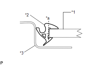
33. REMOVE WINDSHIELD OUTSIDE MOULDING
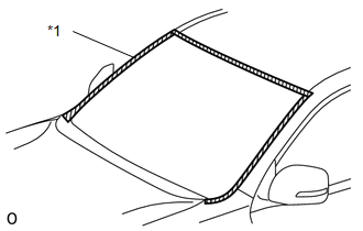
|
(a) Using a knife, cut off the windshield outside moulding as shown in the illustration. NOTICE: Be careful not to damage the vehicle body. |
|
(b) Remove the remaining windshield outside moulding.
Text in Illustration|
*1 |
Windshield Glass |
|
*2 |
Windshield Outside Moulding |
|
*3 |
Vehicle Body |
|
*a |
Cut |
HINT:
Make a partial cut in the windshield outside moulding. Then pull and remove it by hand.
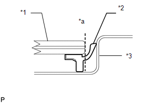
34. REMOVE WINDSHIELD OUTSIDE UPPER MOULDING
|
(a) Using a knife, cut off the windshield outside upper moulding as shown in the illustration. NOTICE: Be careful not to damage the vehicle body. |
|
(b) Pull the shaded area shown in the illustration by hand to remove the windshield outside upper moulding.
Text in Illustration|
*1 |
Windshield Glass |
|
*2 |
Windshield Outside Upper Moulding |
|
*3 |
Vehicle Body |
|
*a |
Cut |
HINT:
Make a partial cut in the windshield outside upper moulding. Then pull and remove it by hand.
35. REMOVE WINDSHIELD GLASS
NOTICE:
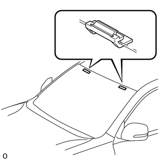
- There are No. 1 and No. 2 windshield glass stoppers on the windshield glass as shown in the illustration. Be careful not to damage the windshield glass when cutting off the adhesive.
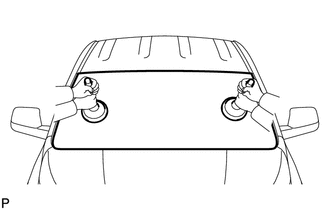
- To prevent the windshield glass from dropping when performing this operation, be sure to hold the windshield glass using suction cups.
HINT:
Depending on the vehicle specifications, a 1-piece or 2-piece type stopper is used.
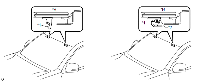 Text in Illustration
|
*A |
for 1-piece Type |
*B |
for 2-piece Type |
|
*1 |
No. 1 Windshield Glass Stopper |
*2 |
No. 2 Windshield Glass Stopper |
|
(a) Apply protective tape around the windshield glass on the vehicle body. Text in Illustration
HINT: Apply protective tape to the installation surface to prevent it from being scratched. |
|
|
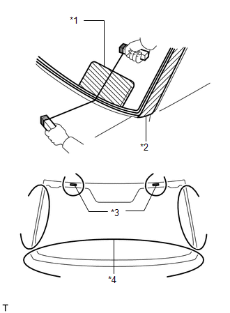
(b) From the interior, insert a piano wire between the vehicle body and windshield glass as shown in the illustration. |
|
(c) Tie objects that can serve as handles (for example, wooden blocks) to both wire ends.
Text in Illustration|
*1 |
Plastic Sheet |
|
*2 |
Protective Tape |
|
*3 |
Windshield Glass Stopper |
|
*4 |
Piano Wire |
NOTICE:
- When separating the windshield glass from the vehicle, be careful not to damage the vehicle paint or interior/exterior ornaments.
- To prevent the instrument panel from being scratched when removing the windshield glass, place a plastic sheet between the piano wire and instrument panel.
|
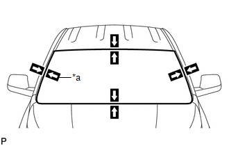
(d) Place matchmarks on the windshield glass and vehicle body at the locations indicated in the illustration. Text in Illustration
NOTICE: Matchmarks do not need to be placed if not reusing the windshield glass. |
|
(e) w/ Windshield Deicer System:
Disconnect the windshield deicer connector.
(f) Cut through the adhesive by pulling the piano wire around the windshield glass.
NOTICE:
Leave as much adhesive on the vehicle body as possible when removing the windshield glass.
(g) Disconnect the stoppers.
|
(h) Using suction cups, remove the windshield glass. |
|
36. REMOVE WINDSHIELD GLASS ADHESIVE DAM
(a) Using a scraper, remove the windshield glass adhesive dam.
37. REMOVE NO. 1 WINDSHIELD GLASS STOPPER (for 1-piece Type)
(a) Using a scraper, remove the 2 No. 1 windshield glass stoppers.
38. REMOVE NO. 2 WINDSHIELD GLASS STOPPER (for 2-piece Type)
(a) Using a scraper, remove the 2 No. 2 windshield glass stoppers.
39. REMOVE NO. 1 WINDSHIELD GLASS STOPPER (for 2-piece Type)
|
(a) Remove the 2 No. 1 windshield glass stoppers. NOTICE: Be sure to replace the No. 1 windshield glass stoppers with new ones. |
|
40. CLEAN WINDSHIELD GLASS
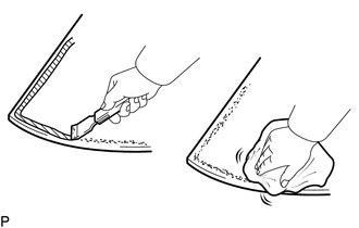
(a) Using a scraper, remove the damaged windshield glass stoppers, windshield glass adhesive dam and adhesive sticking to the windshield glass.
(b) Clean the outer circumference of the windshield glass with non-residue solvent.
NOTICE:
- Do not touch the windshield glass surface after cleaning it.
- Be careful not to damage the windshield glass.
- Even if using new windshield glass, clean the windshield glass with non-residue solvent.
41. CLEAN VEHICLE BODY
|
(a) Clean and shape the contact surface of the vehicle body. (1) On the contact surface of the vehicle body, use a knife to cut away excess adhesive as shown in the illustration. Text in Illustration
NOTICE: Be careful not to damage the vehicle body. HINT: Leave as much adhesive on the vehicle body as possible. |
|
(b) Clean the contact surface of the vehicle body with cleaner.
HINT:
Even if all the adhesive has been removed, clean the vehicle body.
 Components
COMPONENTS
ILLUSTRATION
ILLUSTRATION
ILLUSTRATION
ILLUSTRATION
ILLUSTRATION
ILLUSTRATION
...
 Installation
INSTALLATION
PROCEDURE
1. INSTALL NO. 1 WINDSHIELD GLASS STOPPER
(a) Install 2 new No. 1 windshield glass stoppers to the vehicle body
as shown in the illustration.
Text in Illust ...
Other materials about Toyota 4Runner:
Jam Protection Function does not Operate
DESCRIPTION
This problem may occur in all door windows.
The jam protection function operates within a specified range during
the manual up or auto up operation.
PROCEDURE
1.
PERFORM INITIALIZATION
(a) ...
Open Circuit in IG1/IG2 Power Source Circuit (C1242)
DESCRIPTION
If there is a problem with the master cylinder solenoid (skid control ECU) power
supply circuit, the skid control ECU stores DTCs and prohibits operation under the
fail-safe function.
If the voltage supplied to the IG2 terminal is within the ...
0.0174

.png)