Toyota 4Runner: Installation
INSTALLATION
CAUTION / NOTICE / HINT
HINT:
A bolt without a torque specification is shown in the standard bolt chart (See
page .gif) ).
).
PROCEDURE
1. INSTALL DECK SIDE TRIM CUP HOLDER LH (w/ Rear No. 2 Seat)
(a) Attach the 2 claws to install the deck side trim cup holder LH.
(b) Install the 4 screws.
2. INSTALL DECK SIDE TRIM CUP HOLDER RH (w/ Rear No. 2 Seat)
HINT:
Use the same procedure as for the LH side.
3. INSTALL QUARTER TRIM LID SUB-ASSEMBLY RH (w/ Rear No. 2 Seat)
(a) Attach the 4 claws and 2 guides to install the quarter trim lid sub-assembly RH.
4. INSTALL REAR SEAT SHOULDER BELT HANGER LH (w/ Rear No. 2 Seat)
(a) Attach the claw and guide to install the rear seat shoulder belt hanger LH.
5. INSTALL REAR SEAT SHOULDER BELT HANGER RH (w/ Rear No. 2 Seat)
HINT:
Use the same procedure as for the LH side.
6. INSTALL REAR FLOOR FINISH SIDE PLATE LH (w/o Rear No. 2 Seat)
(a) Attach the claw and 2 guides to install the rear floor finish side plate LH.
(b) Install the 2 screws.
7. INSTALL REAR FLOOR FINISH SIDE PLATE RH (w/o Rear No. 2 Seat)
HINT:
Use the same procedure as for the LH side.
8. INSTALL SIDE TRIM BOX LH (w/o Rear No. 2 Seat)
(a) Attach the 8 claws to install the side trim box LH.
(b) Install the 2 screws.
9. INSTALL SIDE TRIM BOX RH (w/o Rear No. 2 Seat)
HINT:
Use the same procedure as for the LH side.
10. INSTALL REAR COMBINATION LIGHT SERVICE COVER LH
(a) Attach the 2 claws and 2 guides to install the rear combination light service cover LH.
11. INSTALL REAR COMBINATION LIGHT SERVICE COVER RH
HINT:
Use the same procedure as for the LH side.
12. INSTALL QUARTER TRIM JACK COVER SUB-ASSEMBLY
(a) Attach the 3 claws and 2 guides to install the quarter trim jack cover sub-assembly.
13. INSTALL QUARTER TRIM COVER
(a) Attach the 2 claws to install the quarter trim cover.
HINT:
Use the same procedure for the other quarter trim cover.
14. INSTALL REAR NO. 3 SIDE RAIL SPACER LH
(a) Attach the 2 claws to install the rear No. 3 side rail spacer LH.
15. INSTALL REAR NO. 3 SIDE RAIL SPACER RH
HINT:
Use the same procedure as for the LH side.
16. INSTALL ROOF SIDE RAIL GARNISH ASSEMBLY LH
(a) Attach the 3 clips to install the roof side rail garnish assembly LH.
17. INSTALL ROOF SIDE RAIL GARNISH ASSEMBLY RH
HINT:
Use the same procedure as for the LH side.
18. INSTALL FRONT SHOULDER BELT ANCHOR PLATE SUB-ASSEMBLY LH
(a) Attach the 4 claws to install the front shoulder belt anchor plate sub-assembly LH.
19. INSTALL FRONT SHOULDER BELT ANCHOR PLATE SUB-ASSEMBLY RH
HINT:
Use the same procedure as for the LH side.
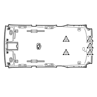
20. INSTALL ROOF HEADLINING ASSEMBLY
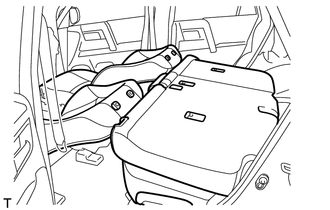
HINT:
Before installing the roof headlining assembly, move the front seats and rear No. 1 seat to the positions shown in the illustration.
(a) Place the roof headlining assembly into the vehicle through the back door.
NOTICE:
Be careful not to damage the roof headlining assembly when placing it in the cabin.
|
(b) w/o Sliding Roof: (1) Install the roof headlining assembly with the 5 clips. |
|
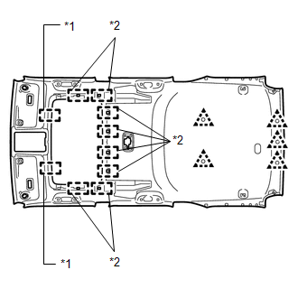
(c) w/ Sliding Roof:
|
(1) Attach the 2 guides and 8 fasteners to install the roof headlining assembly. Text in Illustration
|
|
(2) Install the 5 clips.
(d) Connect the connector and attach the clamp to the rear pillar RH.
(e) Connect the connector and attach the 2 clamps to the front pillar RH.
(f) Connect the connector and attach the 4 clamps to the front pillar LH.
(g) w/ Sliding Roof:
Connect the sliding roof drive gear connector.
(h) w/ EC Mirror:
Connect the inner rear view mirror assembly connector.
21. INSTALL NO. 1 ROOM LIGHT ASSEMBLY
.gif)
22. INSTALL INNER REAR VIEW MIRROR STAY HOLDER COVER (w/ EC Mirror)
.gif)
23. INSTALL MAP LIGHT ASSEMBLY
.gif)
24. INSTALL DRIVE MONITOR SWITCH (w/ Drive Monitor Switch)
.gif)
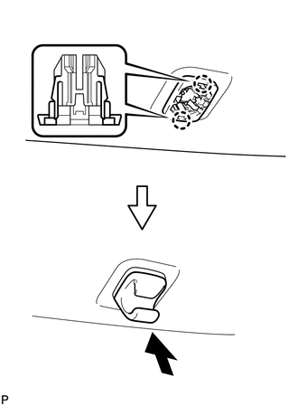
25. INSTALL VISOR HOLDER
|
(a) Attach the 2 claws. |
|
(b) Push in the visor holder to install it.
HINT:
Use the same procedure for the other visor holder.
26. INSTALL VISOR ASSEMBLY LH
(a) Install the visor assembly LH with the 2 screws.
27. INSTALL VISOR ASSEMBLY RH
HINT:
Use the same procedure as for the LH side.
28. INSTALL VISOR BRACKET COVER LH
(a) Attach the 4 claws to install the visor bracket cover LH.
29. INSTALL VISOR BRACKET COVER RH
HINT:
Use the same procedure as for the LH side.
30. INSTALL COAT HOOK
(a) Install the coat hook with the screw.
(b) Attach the claw to close the cover.
HINT:
Use the same procedure for the other coat hook.
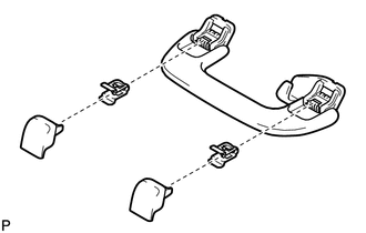
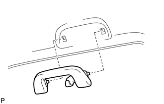
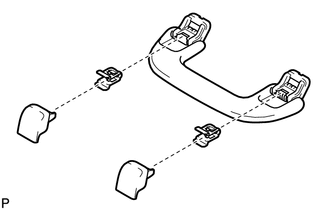
31. INSTALL REAR ASSIST GRIP ASSEMBLY
|
(a) Assemble the rear assist grip assembly as shown in the illustration. |
|
|
(b) Install the rear assist grip assembly. HINT: Use the same procedure for the other rear assist grip assembly. |
|
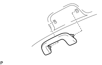
32. INSTALL ASSIST GRIP SUB-ASSEMBLY
|
(a) Assemble the assist grip sub-assembly as shown in the illustration. |
|
|
(b) Install the assist grip sub-assembly. HINT: Use the same procedure for the other assist grip sub-assembly. |
|
33. INSTALL REAR WINDOW SIDE GARNISH ASSEMBLY LH
(a) Pass the rear No. 1 seat outer belt floor anchor through the rear window side garnish assembly LH and attach the 4 claws and 2 guides.
(b) Attach the 7 clips and 4 guides to install the rear window side garnish assembly LH.
34. INSTALL REAR WINDOW SIDE GARNISH ASSEMBLY RH
HINT:
Use the same procedure as for the LH side.
35. INSTALL REAR NO. 2 WINDOW SIDE GARNISH ASSEMBLY LH
(a) w/ Rear No. 2 Seat:
(1) Pass the rear No. 2 seat outer belt floor anchor through the rear No. 2 window side garnish assembly LH and attach the 7 claws and guide.
(b) Attach the 6 clips and guide to install the rear No. 2 window side garnish assembly LH.
36. INSTALL REAR NO. 2 WINDOW SIDE GARNISH ASSEMBLY RH
HINT:
Use the same procedure as for the LH side.
37. INSTALL DECK TRIM SIDE PANEL ASSEMBLY LH
(a) w/o Rear No. 2 Seat:
(1) Pass the rear seatback lock control lever base through the deck trim side panel assembly LH.
(2) Attach the 6 claws and 2 guides to install the rear seatback lock control lever base to the deck trim side panel assembly LH.
(3) Attach the 7 clips, 5 claws and 2 guides to install the deck trim side panel assembly LH.
(4) Install the 3 bolts and 2 screws.
(5) Install the rear No. 1 seat outer belt floor anchor with the bolt.
Torque:
42 N·m {428 kgf·cm, 31 ft·lbf}
(b) w/ Rear No. 2 Seat:
(1) Attach the 7 clips, 5 claws and 2 guides to install the deck trim side panel assembly LH.
(2) Install the 3 bolts and 2 screws.
(3) Install the rear No. 1 seat outer belt floor anchor with the bolt.
Torque:
42 N·m {428 kgf·cm, 31 ft·lbf}
(4) Install the rear No. 2 seat outer belt floor anchor with the bolt.
Torque:
42 N·m {428 kgf·cm, 31 ft·lbf}
38. INSTALL DECK TRIM SIDE PANEL ASSEMBLY RH
(a) w/o Rear No. 2 Seat:
(1) Connect each connector.
(2) Pass the rear seatback lock control lever base through the deck trim side panel assembly RH.
(3) Attach the 6 claws and 2 guides to install the rear seatback lock control lever base to the deck trim side panel assembly RH.
(4) Attach the 7 clips, 5 claws and 2 guides to install the deck trim side panel assembly RH.
(5) Install the 3 bolts and screw.
(6) Install the rear No. 1 seat outer belt floor anchor with the bolt.
Torque:
42 N·m {428 kgf·cm, 31 ft·lbf}
(b) w/ Rear No. 2 Seat:
(1) Connect each connector.
(2) Attach the 7 clips, 5 claws and 2 guides to install the deck trim side panel assembly RH.
(3) Install the 3 bolts and screw.
(4) Install the rear No. 1 seat outer belt floor anchor with the bolt.
Torque:
42 N·m {428 kgf·cm, 31 ft·lbf}
(5) Install the rear No. 2 seat outer belt floor anchor with the bolt.
Torque:
42 N·m {428 kgf·cm, 31 ft·lbf}
39. INSTALL NO. 2 LUGGAGE COMPARTMENT TRIM COVER (w/o Rear No. 2 Seat)
(a) Install the luggage hold belt striker and No. 2 luggage compartment trim cover with the bolt.
(b) Attach the 2 claws to close the cover.
HINT:
Use the same procedure for the other No. 2 luggage compartment trim cover.
40. INSTALL FRONT DECK SIDE TRIM COVER LH
(a) Attach the 2 claws to install the front deck side trim cover LH.
41. INSTALL FRONT DECK SIDE TRIM COVER RH
HINT:
Use the same procedure as for the LH side.
42. INSTALL NO. 1 LUGGAGE COMPARTMENT TRIM HOOK
(a) Push in the No. 1 luggage compartment trim hook to install it.
HINT:
Use the same procedure for the other No. 1 luggage compartment trim hook.
43. INSTALL REAR NO. 1 SEAT OUTER LAP BELT ANCHOR COVER
(a) Attach the 3 claws to install the rear No. 1 seat outer lap belt anchor cover.
HINT:
Use the same procedure for the other rear No. 1 seat outer lap belt anchor cover.
44. INSTALL REAR FLOOR CARPET ASSEMBLY (w/o Deck Board)
(a) Attach the 4 claws to install the rear floor carpet assembly.
45. INSTALL REAR FLOOR MAT REAR SUPPORT PLATE
(a) Attach the 5 clips to install the rear floor mat rear support plate.
46. INSTALL INNER FLOOR SIDE RAIL SUB-ASSEMBLY (w/ Deck Board)
(a) Install the inner floor side rail sub-assembly with the 4 bolts.
47. INSTALL REAR NO. 2 FLOOR BOARD ASSEMBLY (w/ Deck Board)
(a) Attach the 3 clips to install the rear No. 2 floor board assembly.
48. INSTALL NO. 2 DECK BOARD SUB-ASSEMBLY (w/ Deck Board)
(a) Attach the 2 clips and 2 guides to install the No. 2 deck board sub-assembly.
49. INSTALL NO. 2 LUGGAGE COMPARTMENT TRIM COVER (w/ Deck Board)
(a) Install the luggage hold belt striker and No. 2 luggage compartment trim cover with the bolt.
(b) Attach the 2 claws to close the cover.
HINT:
Use the same procedure for the other No. 2 luggage compartment trim cover.
50. INSTALL DECK BOARD ASSEMBLY (w/ Deck Board)
(a) Attach the 2 guides to install the deck board assembly.
(b) Install the 6 bolts.
51. INSTALL LUGGAGE COMPARTMENT SIDE COVER SUB-ASSEMBLY LH (w/ Deck Board)
(a) Attach the 4 clips and 2 guides to install the luggage compartment side cover sub-assembly LH.
52. INSTALL LUGGAGE COMPARTMENT SIDE COVER SUB-ASSEMBLY RH (w/ Deck Board)
HINT:
Use the same procedure as for the LH side.
53. INSTALL NO. 1 DECK BOARD SUB-ASSEMBLY (w/o Deck Board)
(a) Attach the clip to install the No. 1 deck board sub-assembly.
54. INSTALL NO. 1 LUGGAGE COMPARTMENT TRIM COVER (w/o Deck Board)
(a) Install the luggage hold belt striker and No. 1 luggage compartment trim cover with the bolt.
(b) Attach the 4 claws to close the cover.
HINT:
Use the same procedure for the other No. 1 luggage compartment trim cover.
55. INSTALL CENTER PILLAR GARNISH LH
(a) Pass the front seat outer belt floor anchor through the center pillar garnish LH.
(b) Attach the 2 clips and 2 guides to install the center pillar garnish LH.
(c) Install the bolt.
56. INSTALL CENTER PILLAR GARNISH RH
HINT:
Use the same procedure as for the LH side.
57. INSTALL LOWER CENTER PILLAR GARNISH LH
(a) Attach the 4 claws and 2 clips to install the lower center pillar garnish LH.
(b) Install the front seat outer belt floor anchor with the bolt.
Torque:
42 N·m {428 kgf·cm, 31 ft·lbf}
58. INSTALL LOWER CENTER PILLAR GARNISH RH
HINT:
Use the same procedure as for the LH side.
59. INSTALL OUTER LAP BELT ANCHOR COVER
(a) Attach the 3 claws to install the outer lap belt anchor cover.
HINT:
Use the same procedure for the other outer lap belt anchor cover.
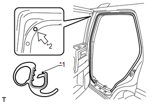
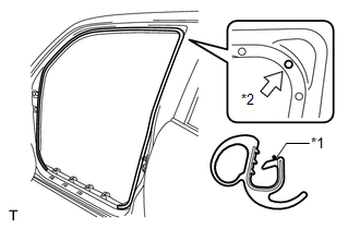
60. INSTALL REAR DOOR OPENING TRIM WEATHERSTRIP LH
|
(a) Align the paint mark on the rear door opening trim weatherstrip LH with the mark position on the vehicle to install the rear door opening trim weatherstrip LH as shown in the illustration. Text in Illustration
|
|
61. INSTALL REAR DOOR OPENING TRIM WEATHERSTRIP RH
HINT:
Use the same procedure as for the LH side.
62. INSTALL REAR DOOR SCUFF PLATE LH
(a) Attach the 3 clips, 6 claws and 2 guides to install the rear door scuff plate LH.
63. INSTALL REAR DOOR SCUFF PLATE RH
HINT:
Use the same procedure as for the LH side.
64. INSTALL QUARTER SCUFF PLATE LH (w/ Rear No. 2 Seat)
(a) Install the quarter scuff plate LH with the 2 bolts.
65. INSTALL QUARTER SCUFF PLATE RH (w/ Rear No. 2 Seat)
HINT:
Use the same procedure as for the LH side.
66. INSTALL REAR NO. 1 FLOOR STEP COVER (w/ Rear No. 2 Seat)
(a) Attach the 2 claws to install the rear No. 1 floor step cover.
HINT:
Use the same procedure for all the rear No. 1 floor step covers.
67. INSTALL FRONT PILLAR GARNISH LH
(a) Remove the protective cover.
(b) Attach the 2 guides and clip to install the front pillar garnish LH.
(c) Install the bolt.
(d) Attach the 2 claws to install the No. 1 front pillar garnish cover LH.
68. INSTALL FRONT PILLAR GARNISH RH
(a) Remove the protective cover.
(b) Attach the clip and 3 guides to install the front pillar garnish RH.
69. INSTALL NO. 1 ASSIST GRIP
(a) Attach the 2 claws to install the No. 1 assist grip.
(b) Install the 2 bolts.
70. INSTALL ASSIST GRIP PLUG
(a) Attach the 2 claws to install the assist grip plug.
HINT:
Use the same procedure for the other assist grip plug.
71. INSTALL FRONT DOOR OPENING TRIM WEATHERSTRIP LH
|
(a) Align the paint mark on the front door opening trim weatherstrip LH with the mark position on the vehicle to install the front door opening trim weatherstrip LH as shown in the illustration. Text in Illustration
|
|
72. INSTALL FRONT DOOR OPENING TRIM WEATHERSTRIP RH
HINT:
Use the same procedure as for the LH side.
73. INSTALL COWL SIDE TRIM BOARD LH
(a) Attach the clip and claw to install the cowl side trim board LH.
(b) Install the clip.
74. INSTALL COWL SIDE TRIM BOARD RH
HINT:
Use the same procedure as for the LH side.
75. INSTALL DOOR SCUFF PLATE ASSEMBLY LH
(a) Attach the 4 clips, 10 claws and 2 guides to install the door scuff plate assembly LH.
76. INSTALL DOOR SCUFF PLATE ASSEMBLY RH
HINT:
Use the same procedure as for the LH side.
77. INSTALL REAR NO. 2 SEAT ASSEMBLY (w/ Rear No. 2 Seat)
(See page .gif) )
)
78. CONNECT CABLE TO NEGATIVE BATTERY TERMINAL
NOTICE:
When disconnecting the cable, some systems need to be initialized after the cable
is reconnected (See page .gif) ).
).
 Reassembly
REASSEMBLY
PROCEDURE
1. INSTALL NO. 2 ANTENNA CORD SUB-ASSEMBLY
(a) w/o Sliding Roof:
Install the No. 2 antenna cord sub-assembly (See page
).
(b) w/ Sliding Roof:
Install the No. 2 antenna co ...
 Lighting (int)
...
Other materials about Toyota 4Runner:
Inspection
INSPECTION
PROCEDURE
1. INSPECT REAR NO. 1 SEAT OUTER BELT ASSEMBLY RH
NOTICE:
Do not disassemble the retractor.
(a) When the inclination of the retractor is 15° or less, check that the belt
can be pulled from the retractor. When the inclination of t ...
System Description
SYSTEM DESCRIPTION
1. DESCRIPTION
(a) Safety Connect performs ACN (Automatic Collision Notification), manual emergency
calling, stolen vehicle tracking and roadside assistance service, by audio and data
communications between the vehicle and call center ...
0.0144

