Toyota 4Runner: Reassembly
REASSEMBLY
PROCEDURE
1. INSTALL FRONT SHOCK ABSORBER BUSH
|
(a) Using SST and a press, install a new absorber bush. SST: 09710-30012 09710-04071 09710-04081 |
|
.png)
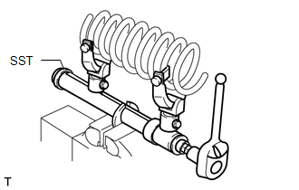
2. INSTALL FRONT COIL SPRING LH
|
(a) Attach SST to the front coil spring and secure it in a vise. SST: 09727-30021 09727-00010 09727-00031 SST: 09727-00060 |
|
|
(b) Attach the arm of SST to the diameter of the front coil spring. CAUTION:
|
|
.png)
(c) Using SST, compress the front coil spring.
CAUTION:
- If the front coil spring bends during the compression, immediately stop the compression and reinstall SST.
- Do not compress the spring until the coil springs contact each other.
- Do not use an impact wrench. It will damage SST.
|
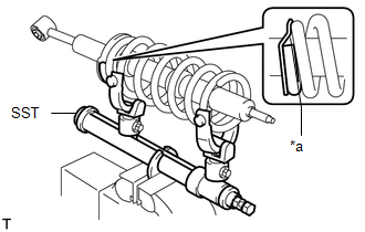
(d) Install the front coil spring onto the front shock absorber assembly. Text in Illustration
NOTICE: Make sure to fit the end of the spring that has the larger diameter into the front shock absorber lower seat. HINT: Fit the lower end of the front coil spring into the gap of the front shock absorber lower seat. |
|
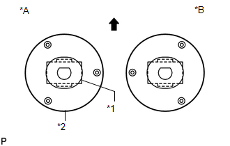
3. INSTALL FRONT SUSPENSION SUPPORT SUB-ASSEMBLY LH
(a) Install the cushion, 2 retainers and suspension support to the piston rod.
(b) Temporarily install a new front shock absorber nut to the suspension support.
(c) Position the suspension support as shown in the illustration.
Text in Illustration|
*A |
LH |
|
*B |
RH |
|
*1 |
Absorber Bush |
|
*2 |
Suspension Support Sub-assembly |
.png) |
Front |
(d) Remove SST.
HINT:
Release the coil spring while checking the position of the suspension support.
NOTICE:
Do not use an impact wrench. It will damage the shock absorber rod.
4. TIGHTEN FRONT SUPPORT TO FRONT SHOCK ABSORBER NUT
(a) Tighten a new nut.
Torque:
25 N·m {255 kgf·cm, 18 ft·lbf}
 Inspection
INSPECTION
PROCEDURE
1. INSPECT FRONT SHOCK ABSORBER ASSEMBLY LH
(a) Compress and extend the shock absorber rod and check that there is no abnormal
resistance or unusual sound during operation.
...
 Installation
INSTALLATION
CAUTION / NOTICE / HINT
NOTICE:
Be sure to read the precaution before performing this procedure (See page
).
HINT:
Use the same procedure for the RH and LH sides.
The p ...
Other materials about Toyota 4Runner:
System Description
SYSTEM DESCRIPTION
1. GENERAL
(a) To assist the driver with parking the vehicle by displaying an image of the
area behind the vehicle, this system has a rear television camera assembly mounted
on the back door. The system displays the image on the radio ...
On-vehicle Inspection
ON-VEHICLE INSPECTION
CAUTION / NOTICE / HINT
CAUTION:
Be sure to follow the correct removal and installation procedures for the occupant
classification ECU.
PROCEDURE
1. CHECK OCCUPANT CLASSIFICATION ECU (VEHICLE NOT INVOLVED IN COLLISION)
(a) Perform ...

0.0092