Toyota 4Runner: Installation
INSTALLATION
PROCEDURE
1. INSTALL NO. 1 ULTRASONIC SENSOR RETAINER
|
(a) Align the keyhole and protrusion as shown in the illustration. Text in Illustration
|
|
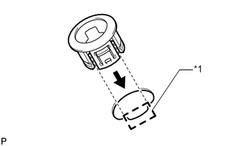
(b) Attach the 4 claws to install the No. 1 ultrasonic sensor retainer to the rear bumper cover.
NOTICE:
Do not damage the bumper cover with the protrusion when installing the No. 1 ultrasonic sensor retainer.
HINT:
Use the same procedure as for the other side.
2. INSTALL NO. 2 ULTRASONIC SENSOR RETAINER
|
(a) Align the keyhole and protrusion as shown in the illustration. Text in Illustration
|
|
.png)
(b) Attach the 3 claws to install the No. 2 ultrasonic sensor retainer to the rear bumper cover.
NOTICE:
Do not damage the bumper cover with the protrusion when installing the No. 2 ultrasonic sensor retainer.
HINT:
Use the same procedure as for the other side.
3. INSTALL ULTRASONIC SENSOR CLIP
(a) Attach the claw to install the ultrasonic sensor clip to the No. 1 ultrasonic sensor.
HINT:
Use the same procedure as for the other side.
4. INSTALL NO. 1 ULTRASONIC SENSOR
(a) Attach the 2 claws to install the No. 1 ultrasonic sensor to the ultrasonic sensor retainer.
HINT:
Use the same procedure as for the other side.
5. INSTALL NO. 3 FLOOR WIRE
.gif)
6. INSTALL REAR BUMPER COVER
7. INSTALL REAR QUARTER PANEL MUDGUARD LH
8. INSTALL REAR QUARTER PANEL MUDGUARD RH
HINT:
Use the same procedure as for the LH side.
9. INSTALL JACK BOX HOLE COVER
 Inspection
INSPECTION
PROCEDURE
1. INSPECT NO. 1 ULTRASONIC SENSOR
(a) Measure the resistance according to the value(s) in the table below.
Standard Resistance:
Tester Connection
Co ...
 Brake (front)
...
Other materials about Toyota 4Runner:
Installation
INSTALLATION
PROCEDURE
1. INSTALL LOWER NO. 1 INSTRUMENT PANEL AIRBAG ASSEMBLY
(a) Connect the connector.
NOTICE:
When handling the airbag connector, take care not to damage the airbag
wire harness.
...
Multi-terrain Select Indicator Light Remains ON
DESCRIPTION
Refer to Multi-terrain Select Indicator Light does not Come ON (See page
).
WIRING DIAGRAM
Refer to Multi-terrain Select Indicator Light does not Come ON (See page
).
PROCEDURE
1.
READ VALUE USING TECHSTREAM (OFF-ROA ...

0.007