Toyota 4Runner: Inspection
INSPECTION
PROCEDURE
1. INSPECT NO. 1 ULTRASONIC SENSOR
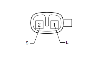
(a) Measure the resistance according to the value(s) in the table below.
Standard Resistance:
|
Tester Connection |
Condition |
Specified Condition |
|---|---|---|
|
1 (E) - 2 (S) |
Always |
20 to 40 kΩ |
If the result is not as specified, replace the No. 1 ultrasonic sensor.
 Removal
REMOVAL
PROCEDURE
1. REMOVE JACK BOX HOLE COVER
2. REMOVE REAR QUARTER PANEL MUDGUARD LH
3. REMOVE REAR QUARTER PANEL MUDGUARD RH
HINT:
Use the same procedure as for the LH side.
4. REMOV ...
 Installation
INSTALLATION
PROCEDURE
1. INSTALL NO. 1 ULTRASONIC SENSOR RETAINER
(a) Align the keyhole and protrusion as shown in the illustration.
Text in Illustration
*1
...
Other materials about Toyota 4Runner:
How To Proceed With Troubleshooting
HOW TO PROCEED WITH TROUBLESHOOTING
1. OPERATION FLOW
HINT:
Perform troubleshooting in accordance with the procedures below. The following
is an outline of basic troubleshooting procedures. Confirm the troubleshooting procedures
for the circuit you are ...
Diagnosis System
DIAGNOSIS SYSTEM
1. DESCRIPTION
(a) Smart key system (for start function) data and the Diagnostic Trouble Codes
(DTCs) can be read through the Data Link Connector 3 (DLC3) of the vehicle. When
the function seems to be malfunctioning, use the Techstream t ...

0.0132