Toyota 4Runner: Instrument Panel Speaker
Components
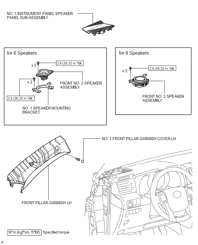
COMPONENTS
ILLUSTRATION
Removal
REMOVAL
CAUTION / NOTICE / HINT
HINT:
- Use the same procedure for both the RH and LH sides.
- The procedure listed below is for the LH side.
PROCEDURE
1. REMOVE FRONT PILLAR GARNISH LH
.gif)
2. REMOVE NO. 1 INSTRUMENT PANEL SPEAKER PANEL SUB-ASSEMBLY
3. REMOVE FRONT NO. 2 SPEAKER ASSEMBLY
(a) Remove the 2 screws.
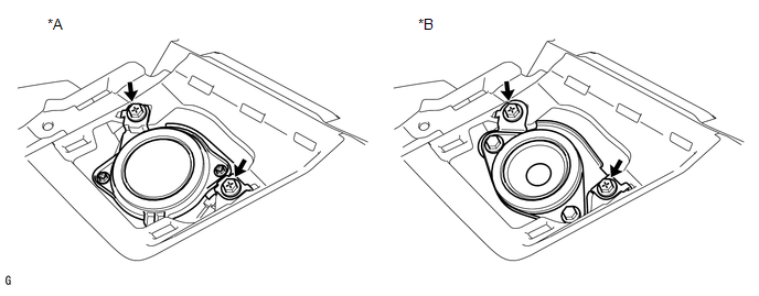 Text in Illustration
|
*A |
for 9 Speakers |
*B |
for 8 Speakers |
(b) Disconnect the connector to remove the front No. 2 speaker assembly.
NOTICE:
Do not touch the cone of the front No. 2 speaker assembly.
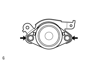
4. REMOVE NO. 1 SPEAKER MOUNTING BRACKET (for 8 Speakers)
|
(a) Remove the 2 bolts and No. 1 speaker mounting bracket. |
|
Inspection
INSPECTION
PROCEDURE
1. INSPECT FRONT NO. 2 SPEAKER ASSEMBLY
(a) Temporarily replace the front No. 2 speaker assembly with a new or normally functioning one.
OK:
Malfunction disappears.
Installation
INSTALLATION
CAUTION / NOTICE / HINT
HINT:
- Use the same procedure for both the RH and LH sides.
- The procedure listed below is for the LH side.
PROCEDURE
1. INSTALL NO. 1 SPEAKER MOUNTING BRACKET (for 8 Speakers)
(a) Install the No. 1 speaker mounting bracket with the 2 bolts.
Torque:
2.5 N·m {25 kgf·cm, 22 in·lbf}
2. INSTALL FRONT NO. 2 SPEAKER ASSEMBLY
(a) Connect the connector.
(b) Align the positioning pins of the front No. 2 speaker assembly with the instrument panel sub-assembly to temporarily install the front No. 2 speaker assembly.
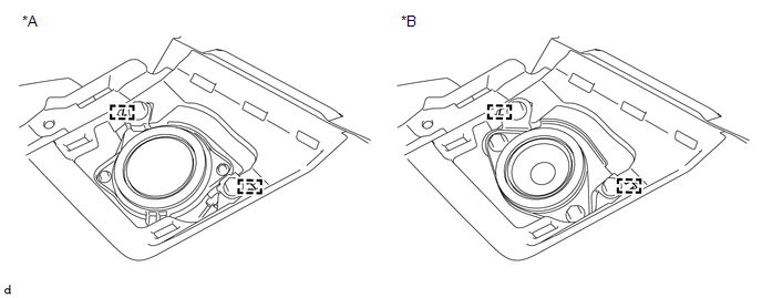 Text in Illustration
|
*A |
for 9 Speakers |
*B |
for 8 Speakers |
(c) Install the front No. 2 speaker assembly with the 2 screws.
Torque:
2.5 N·m {25 kgf·cm, 22 in·lbf}
NOTICE:
- Do not touch the cone of the front No. 2 speaker assembly.
- When installing the front No. 2 speaker assembly to the instrument panel sub-assembly, be careful that the wires do not get caught between the parts.
3. INSTALL NO. 1 INSTRUMENT PANEL SPEAKER PANEL SUB-ASSEMBLY
.gif)
4. INSTALL FRONT PILLAR GARNISH LH
 Front Door Speaker
Components
COMPONENTS
ILLUSTRATION
Removal
REMOVAL
CAUTION / NOTICE / HINT
HINT:
Use the same procedure for the RH and LH sides.
The procedure listed below is for the LH side. ...
 Luggage Speaker
...
Other materials about Toyota 4Runner:
Shifting between H4 and L4
Shifting from H4 to L4
Stop the vehicle completely and
continue to depress the brake pedal.
Shift the shift lever to N.
Type A
Shift the front-wheel drive
control lever to L4.
Type B
Push the “UNLOCK” button and
then push and turn the front ...
Problem Symptoms Table
PROBLEM SYMPTOMS TABLE
HINT:
Use the table below to help determine the cause of problem symptoms. If multiple
suspected areas are listed, the potential causes of the symptoms are listed in order
of probability in the "Suspected Area" column of ...

0.0091