Toyota 4Runner: Front Door Speaker
Components
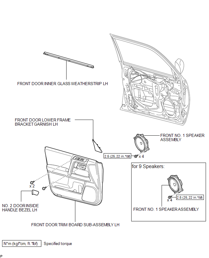
COMPONENTS
ILLUSTRATION
Removal
REMOVAL
CAUTION / NOTICE / HINT
HINT:
- Use the same procedure for the RH and LH sides.
- The procedure listed below is for the LH side.
PROCEDURE
1. REMOVE FRONT DOOR LOWER FRAME BRACKET GARNISH LH
.gif)
2. REMOVE NO. 2 DOOR INSIDE HANDLE BEZEL LH
3. REMOVE FRONT DOOR INNER GLASS WEATHERSTRIP LH
4. REMOVE FRONT DOOR TRIM BOARD SUB-ASSEMBLY LH
5. REMOVE FRONT NO. 1 SPEAKER ASSEMBLY
|
(a) Disconnect the speaker connector. |
|
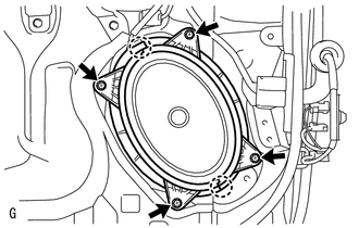
(b) Remove the 4 screws.
(c) Detach the 2 claws and remove the speaker.
NOTICE:
Do not touch the cone of the speaker.
Inspection
INSPECTION
PROCEDURE
1. INSPECT FRONT NO. 1 SPEAKER ASSEMBLY (for 8 Speakers)
|
(a) Measure the resistance according to the value(s) in the table below. Standard Resistance:
If the result is not as specified, replace the speaker assembly. Text in Illustration
|
|
.png)
2. INSPECT FRONT NO. 1 SPEAKER ASSEMBLY (for 9 Speakers)
|
(a) Measure the resistance according to the value(s) in the table below. Standard Resistance:
If the result is not as specified, replace the speaker assembly. Text in Illustration
|
|
Installation
INSTALLATION
CAUTION / NOTICE / HINT
HINT:
- Use the same procedure for the RH and LH sides.
- The procedure listed below is for the LH side.
PROCEDURE
1. INSTALL FRONT NO. 1 SPEAKER ASSEMBLY
(a) Temporarily install the speaker by attaching the 2 claws of the speaker to the door panel.
(b) Install the speaker with the 4 screws.
Torque:
2.5 N·m {25 kgf·cm, 22 in·lbf}
NOTICE:
Do not touch the cone of the speaker.
(c) Connect the connector.
2. INSTALL FRONT DOOR INNER GLASS WEATHERSTRIP LH
.gif)
3. INSTALL FRONT DOOR TRIM BOARD SUB-ASSEMBLY LH
4. INSTALL NO. 2 DOOR INSIDE HANDLE BEZEL LH
5. INSTALL FRONT DOOR LOWER FRAME BRACKET GARNISH LH
 Back Door Speaker
Components
COMPONENTS
ILLUSTRATION
Removal
REMOVAL
CAUTION / NOTICE / HINT
HINT:
Use the same procedure for the RH and LH sides.
The procedure listed below is for the LH side. ...
 Instrument Panel Speaker
Components
COMPONENTS
ILLUSTRATION
Removal
REMOVAL
CAUTION / NOTICE / HINT
HINT:
Use the same procedure for both the RH and LH sides.
The procedure listed below is for the LH ...
Other materials about Toyota 4Runner:
How To Proceed With Troubleshooting
CAUTION / NOTICE / HINT
HINT:
Use the following procedure to troubleshoot the audio and visual system.
*: Use the Techstream.
PROCEDURE
1.
VEHICLE BROUGHT TO WORKSHOP
NEXT
...
Downhill Assist Control Indicator Light Remains ON
DESCRIPTION
When the downhill assist control switch is turned on, the downhill assist control
function is available and the downhill assist control indicator light illuminates.
WIRING DIAGRAM
Refer to Downhill Assist Control Indicator Light does not Come ...

0.0108