Toyota 4Runner: Lost Communication with Front Airbag Sensor LH (B1617/84,B1618/84)
DESCRIPTION
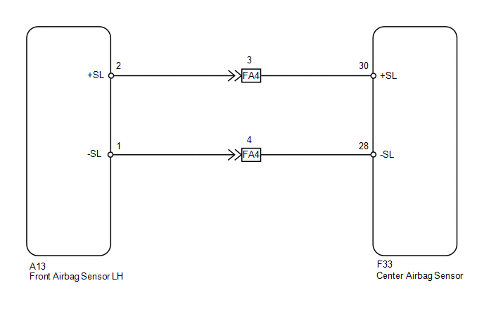
The front airbag sensor LH circuit consists of the center airbag sensor and front airbag sensor LH.
The front airbag sensor LH detects impacts to the vehicle and sends signals to the center airbag sensor to determine if the airbag should be deployed.
DTC B1617/84 or B1618/84 is stored when a malfunction is detected in the front airbag sensor LH circuit.
|
DTC Code |
DTC Detection Condition |
Trouble Area |
|---|---|---|
|
B1617/84 |
One of the following conditions is met:
|
|
|
B1618/84 |
One of the following conditions is met:
|
|
WIRING DIAGRAM
CAUTION / NOTICE / HINT
NOTICE:
When disconnecting the cable from the negative (-) battery terminal while performing
repairs, some systems need to be initialized after the cable is reconnected (See
page .gif) ).
).
PROCEDURE
|
1. |
CHECK CONNECTION OF CONNECTORS |
(a) Turn the ignition switch off.
(b) Disconnect the cable from the negative (-) battery terminal, and wait for at least 90 seconds.
(c) Check that the connectors are properly connected to the center airbag sensor and front airbag sensor LH.
OK:
The connectors are properly connected.
| NG | .gif) |
CONNECT CONNECTORS PROPERLY |
|
.gif)
|
2. |
CHECK CONNECTORS |
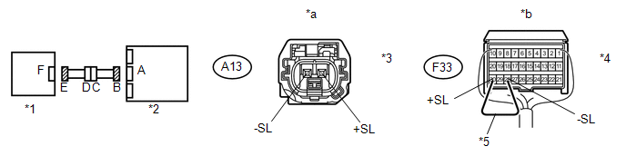
(a) Disconnect the connectors from the center airbag sensor and front airbag sensor LH.
|
(b) Check that the connectors (on the center airbag sensor side and front airbag sensor LH side) are not damaged. OK: The connectors are not deformed or damaged. Text in Illustration
|
|
| NG | |
REPLACE HARNESS AND CONNECTOR |
|
|
3. |
CHECK FRONT AIRBAG SENSOR LH CIRCUIT |
(a) Connect the cable to the negative (-) battery terminal, and wait for at least 2 seconds.
 Text in Illustration
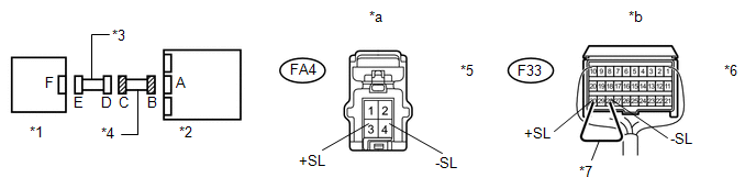
|
*1 |
Front Airbag Sensor LH |
*2 |
Center Airbag Sensor |
|
*3 |
Connector E |
*4 |
Connector B |
|
*5 |
Service Wire |
- |
- |
|
*a |
Front view of wire harness connector (to Front Airbag Sensor LH) |
*b |
Rear view of wire harness connector (to Center Airbag Sensor) |
(b) Measure the voltage according to the value(s) in the table below.
Standard Voltage:
|
Tester Connection |
Switch Condition |
Specified Condition |
|---|---|---|
|
A13-2 (+SL) - Body ground |
Ignition switch ON |
Below 1 V |
|
A13-1 (-SL) - Body ground |
Ignition switch ON |
Below 1 V |
(c) Turn the ignition switch off.
(d) Disconnect the cable from the negative (-) battery terminal, and wait for at least 90 seconds.
(e) Using a service wire, connect terminals 30 (+SL) and 28 (-SL) of connector B.
NOTICE:
Do not forcibly insert the service wire into the terminals of the connector when connecting a service wire.
(f) Measure the resistance according to the value(s) in the table below.
Standard Resistance:
|
Tester Connection |
Condition |
Specified Condition |
|---|---|---|
|
A13-2 (+SL) - A13-1 (-SL) |
Always |
Below 1 Ω |
(g) Disconnect the service wire from connector B.
(h) Measure the resistance according to the value(s) in the table below.
Standard Resistance:
|
Tester Connection |
Condition |
Specified Condition |
|---|---|---|
|
A13-2 (+SL) - A13-1 (-SL) |
Always |
1 MΩ or higher |
|
A13-2 (+SL) - Body ground |
Always |
1 MΩ or higher |
|
A13-1 (-SL) - Body ground |
Always |
1 MΩ or higher |
| NG | |
GO TO STEP 5 |
|
|
4. |
CHECK FRONT AIRBAG SENSOR LH |
|
(a) Connect the connectors to the center airbag sensor. |
|
(b) Interchange the front airbag sensor LH with RH and connect the connectors to them.
(c) Connect the cable to the negative (-) battery terminal, and wait for at least 2 seconds.
(d) Turn the ignition switch to ON, and wait for at least 60 seconds.
(e) Clear the DTCs stored in memory (See page
).
(f) Turn the ignition switch off.
(g) Turn the ignition switch to ON, and wait for at least 60 seconds.
(h) Check for DTCs (See page ).
Result
|
Result |
Proceed to |
|---|---|
|
DTC B1617 or B1618 is output |
A |
|
DTC B1612 or B1613 is output |
B |
|
DTC B1612, B1613, B1617 and B1618 are not output |
C |
HINT:
Codes other than DTC B1612, B1613, B1617 and B1618 may be output at this time, but they are not related to this check.
Text in Illustration|
*1 |
Front Airbag Sensor RH |
|
*2 |
Center Airbag Sensor |
| C | |
USE SIMULATION METHOD TO CHECK |
| A | |
REPLACE CENTER AIRBAG SENSOR ASSEMBLY |
| B | |
REPLACE FRONT AIRBAG SENSOR LH |
|
5. |
CHECK INSTRUMENT PANEL WIRE (CENTER AIRBAG SENSOR - ENGINE ROOM MAIN WIRE) |
(a) Disconnect the instrument panel wire connector from the engine room main wire.
 Text in Illustration
|
*1 |
Front Airbag Sensor LH |
*2 |
Center Airbag Sensor |
|
*3 |
Engine Room Main Wire |
*4 |
Instrument Panel Wire |
|
*5 |
Connector C |
*6 |
Connector B |
|
*7 |
Service Wire |
- |
- |
|
*a |
Front view of wire harness connector (to Engine Room Main Wire) |
*b |
Rear view of wire harness connector (to Center Airbag Sensor) |
(b) Connect the cable to the negative (-) battery terminal, and wait for at least 2 seconds.
(c) Measure the voltage according to the value(s) in the table below.
Standard Voltage:
|
Tester Connection |
Switch Condition |
Specified Condition |
|---|---|---|
|
FA4-2 (+SL) - Body ground |
Ignition switch ON |
Below 1 V |
|
FA4-1 (-SL) - Body ground |
Ignition switch ON |
Below 1 V |
(d) Turn the ignition switch off.
(e) Disconnect the cable from the negative (-) battery terminal, and wait for at least 90 seconds.
(f) Using a service wire, connect terminals 30 (+SL) and 28 (-SL) of connector B.
NOTICE:
Do not forcibly insert the service wire into the terminals of the connector when connecting a service wire.
(g) Measure the resistance according to the value(s) in the table below.
Standard Resistance:
|
Tester Connection |
Condition |
Specified Condition |
|---|---|---|
|
FA4-2 (+SL) - FA4-1 (-SL) |
Always |
Below 1 Ω |
(h) Disconnect the service wire from connector B.
(i) Measure the resistance according to the value(s) in the table below.
Standard Resistance:
|
Tester Connection |
Condition |
Specified Condition |
|---|---|---|
|
FA4-2 (+SL) - FA4-1 (-SL) |
Always |
1 MΩ or higher |
|
FA4-2 (+SL) - Body ground |
Always |
1 MΩ or higher |
|
FA4-1 (-SL) - Body ground |
Always |
1 MΩ or higher |
| OK | |
REPLACE ENGINE ROOM MAIN WIRE |
| NG | |
REPLACE INSTRUMENT PANEL WIRE |
 Lost Communication with Front Satellite Sensor Bus (B161A/8A)
DESCRIPTION
The front collision sensor circuit (front airbag sensor RH circuit and front
airbag sensor LH circuit) is composed of the center airbag sensor assembly, front
airbag sensor RH and fro ...
 Lost Communication with Front Airbag Sensor RH (B1612/83,B1613/83)
DESCRIPTION
The front airbag sensor RH circuit consists of the center airbag sensor and front
airbag sensor RH.
The front airbag sensor RH detects impacts to the vehicle and sends signals to
the ...
Other materials about Toyota 4Runner:
Dtc Check / Clear
DTC CHECK / CLEAR
1. CHECK DTC (USING TECHSTREAM)
(a) Turn the ignition switch off.
(b) Connect the Techstream to the DLC3.
(c) Turn the ignition switch to ON.
(d) Turn the Techstream on.
(e) Enter the following menus: Chassis / Tire Pressure Monitor / T ...
Security Indicator Light Circuit
DESCRIPTION
When the engine immobiliser system is set, the security indicator flashes
continuously, but does not illuminate if the engine immobiliser system is
not set.
WIRING DIAGRAM
CAUTION / NOTICE / HINT
NOTICE:
Before replacing ...

0.0266