Toyota 4Runner: Mayday Battery
Components
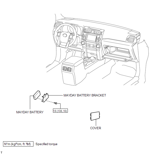
COMPONENTS
ILLUSTRATION
Removal
REMOVAL
PROCEDURE
1. DISCONNECT CABLE FROM NEGATIVE BATTERY TERMINAL
NOTICE:
When disconnecting the cable, some systems need to be initialized after the cable
is reconnected (See page .gif) ).
).
2. REMOVE MAYDAY BATTERY WITH BRACKET
|
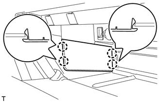
(a) Detach the 4 claws and remove the cover. |
|
|
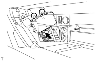
(b) Remove the bolt and detach the 2 claws. |
|
|
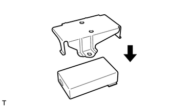
(c) Move the mayday battery with bracket as shown in the illustration. |
|
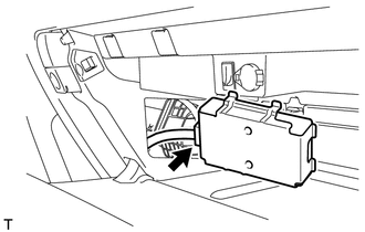
(d) Disconnect the connector and remove the mayday battery with bracket.
3. REMOVE MAYDAY BATTERY
|
(a) Remove the bracket from the mayday battery. |
|

Installation
INSTALLATION
PROCEDURE
1. INSTALL MAYDAY BATTERY
|
(a) Install the bracket to the battery. |
|
2. INSTALL MAYDAY BATTERY WITH BRACKET
|
(a) Connect the connector. |
|
.png)
|
(b) Attach the 2 claws and install the mayday battery with bracket with the bolt. Torque: 13 N·m {133 kgf·cm, 10 ft·lbf} |
|
.png)
|
(c) Attach the 4 claws to install the cover. |
|
.png)
3. CONNECT CABLE TO NEGATIVE BATTERY TERMINAL
NOTICE:
When disconnecting the cable, some systems need to be initialized after the cable
is reconnected (See page .gif) ).
).
4. CHECK SRS WARNING LIGHT
(a) Check the SRS warning light (See page ).
5. PERFORM REGISTRATION
(a) Perform registration (See page ).
NOTICE:
When replacing the mayday battery or DCM (telematics transceiver) together with the mayday battery, perform registration.
 Manual(sos)switch
Components
COMPONENTS
ILLUSTRATION
ILLUSTRATION
Installation
INSTALLATION
PROCEDURE
1. INSTALL TELEPHONE SWITCH ASSEMBLY
(a) Install the telephone switch with the 2 screws.
(b) Connec ...

Other materials about Toyota 4Runner:
Power Source Mode does not Change to ON (IG)
DESCRIPTION
When the engine switch is pushed with the key in the cabin, the power management
control ECU receives signals to switch the power source mode.
WIRING DIAGRAM
Refer to "Power Source Mode does not Change to on (IG and ACC)" (See page
...
Removal
REMOVAL
PROCEDURE
1. REMOVE UPPER RADIATOR SUPPORT SEAL
2. REMOVE FRONT BUMPER COVER
(a) Put protective tape around the front bumper cover.
(b) Remove the 3 bolts, 10 screws and 6 clips.
(c) Detach the 14 claws to remove the front bumper cover with ra ...

0.0079