Toyota 4Runner: Manual(sos)switch
Components
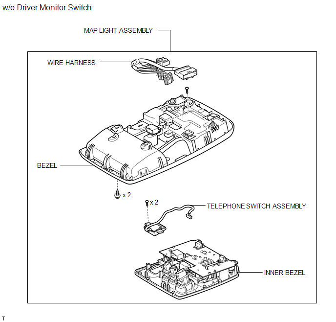
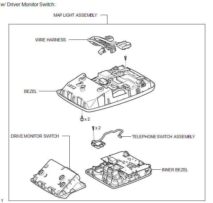
COMPONENTS
ILLUSTRATION
ILLUSTRATION
Installation
INSTALLATION
PROCEDURE
1. INSTALL TELEPHONE SWITCH ASSEMBLY
(a) Install the telephone switch with the 2 screws.
(b) Connect the connector.
(c) Attach the 8 claws to install the inner bezel.
(d) Install the screw.
(e) Connect the 6 connectors.
2. INSTALL MAP LIGHT ASSEMBLY
.gif)
3. INSTALL DRIVE MONITOR SWITCH
Removal
REMOVAL
PROCEDURE
1. REMOVE DRIVE MONITOR SWITCH
.gif)
2. REMOVE MAP LIGHT ASSEMBLY
3. REMOVE TELEPHONE SWITCH ASSEMBLY
|
(a) Disconnect the 6 connectors. |
|
.png)
|
(b) Remove the screw. |
|
.png)
|
(c) Detach the 8 claws and remove the inner bezel. |
|
.png)
|
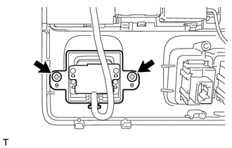
(d) Remove the 2 screws and telephone switch. |
|
 Installation
INSTALLATION
PROCEDURE
1. INSTALL NO. 2 TELEPHONE BRACKET
(a) Install the bracket with the 2 bolts.
2. INSTALL NO. 1 TELEPHONE BRACKET
(a) Install the bracket with the 3 bolts.
(b) Connect the 2 ...
 Mayday Battery
Components
COMPONENTS
ILLUSTRATION
Removal
REMOVAL
PROCEDURE
1. DISCONNECT CABLE FROM NEGATIVE BATTERY TERMINAL
NOTICE:
When disconnecting the cable, some systems need to be initialized ...
Other materials about Toyota 4Runner:
Diagnosis System
DIAGNOSIS SYSTEM
1. DESCRIPTION
(a) Lighting system data and the Diagnostic Trouble Codes (DTCs) can be read
from the Data Link Connector 3 (DLC3) of the vehicle. When the system seems to be
malfunctioning, use the Techstream to check for malfunctions an ...
How To Proceed With Troubleshooting
CAUTION / NOTICE / HINT
Use these procedures to troubleshoot the clock system.
PROCEDURE
1.
VEHICLE BROUGHT TO WORKSHOP
NEXT
2.
INSPECT ...

0.0077