
Toyota 4Runner: Monitor Drive Pattern
MONITOR DRIVE PATTERN
1. TEST MONITOR DRIVE PATTERN FOR ECT
CAUTION:
Perform this drive pattern on a level surface and strictly observe the posted speed limits and traffic laws while driving.
HINT:
Performing this drive pattern is one method to simulate the malfunction detection conditions of the ECT.
The DTCs may not be detected through ordinary, everyday driving. Also, DTCs may not be detected through this drive pattern.
(a) Preparation for driving
(1) Warm up the engine sufficiently (engine coolant temperature is 60°C (140°F) or higher).
(2) Drive the vehicle when the atmospheric temperature is -10°C (14°F) or higher.
Malfunctions are not detected when the atmospheric temperature is less than -10°C (14°F).
(b) Drive pattern
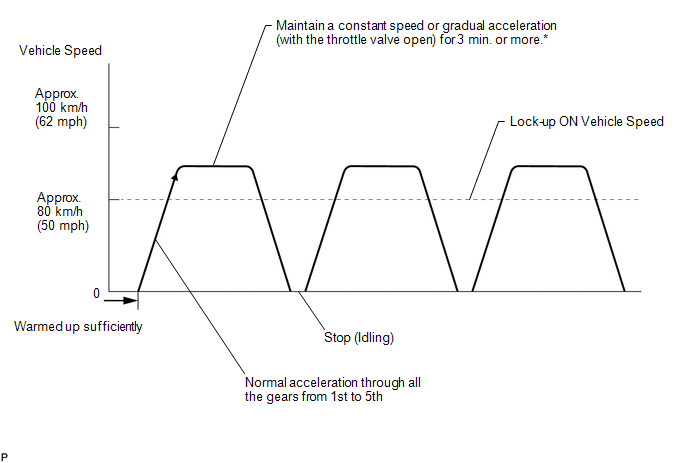
(1) Drive the vehicle through all the gears.
Stop → 1st → 2nd → 3rd → 4th → 5th → 5th (lock-up ON).
(2) Repeat the above drive pattern 3 times or more.
NOTICE:
- When using the Techstream, the monitor status can be checked in the
Data List (See page
.gif) ).
). - In the event that the drive pattern must be interrupted (due to traffic conditions or other factors), the drive pattern can be resumed and, in most cases, the monitor can be completed.
HINT:
*: Drive at such a speed in the uppermost gear so as to engage lock-up. The vehicle can be driven at a speed lower than the speed shown in the above diagram in lock-up.
NOTICE:
It is necessary to drive the vehicle for approximately 30 minutes to detect DTC P0711 (No. 1 ATF temperature sensor malfunction).
 Initialization
INITIALIZATION
1. RESET MEMORY
NOTICE:
Perform Reset Memory (AT initialization) when replacing the automatic
transmission assembly, valve body assembly or any of the shift solenoid
...
 Problem Symptoms Table
PROBLEM SYMPTOMS TABLE
HINT:
Use the table below to help determine the cause of problem symptoms.
If multiple suspected areas are listed, the potential causes of the symptoms
are lis ...
Other materials about Toyota 4Runner:
Terminals Of Ecu
TERMINALS OF ECU
1. TERMINALS OF ECU
Text in Illustration
*a
Component without harness connected
(Skid Control ECU)
-
-
Terminal No. (Symbol)
Terminal Description
...
Removal
REMOVAL
PROCEDURE
1. REMOVE NO. 1 INSTRUMENT CLUSTER FINISH PANEL GARNISH
2. REMOVE NO. 2 INSTRUMENT CLUSTER FINISH PANEL GARNISH
3. REMOVE HEATER CONTROL ASSEMBLY
4. REMOVE SHIFT LEVER KNOB SUB-ASSEMBLY
5. REMOVE SHIFT LEVER KNOB SUB-ASSEMBL ...

0.0153