Toyota 4Runner: Removal
REMOVAL
PROCEDURE
1. REMOVE JACK BOX HOLE COVER
|
(a) Put protective around the jack box hole cover. |
|
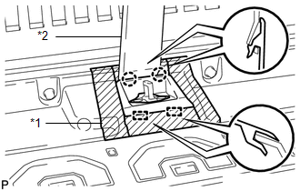
(b) Using a moulding remover, Detach the 2 claws and 2 guides and remove the jack box hole cover.
Text in Illustration|
*1 |
Protective Tape |
|
*2 |
Moulding Remover |
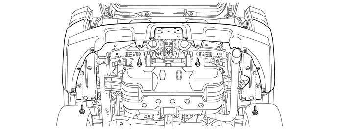
2. REMOVE REAR QUARTER PANEL MUDGUARD LH
.gif)
3. REMOVE REAR QUARTER PANEL MUDGUARD RH
HINT:
Use the same procedure as for the LH side.
4. REMOVE REAR BUMPER COVER
(a) Remove the 2 bolts and 2 screws.
(b) Put protective tape around the rear bumper cover.
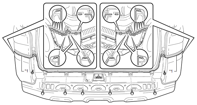 Text in Illustration
|
*1 |
Protective Tape |
- |
- |
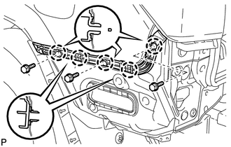
(c) Remove the 2 screws and 6 bolts.
(d) Detach the 18 claws to remove the rear bumper cover.
5. REMOVE REAR BUMPER ENERGY ABSORBER
|
(a) Remove the rear bumper energy absorber. |
|
6. REMOVE REAR BUMPER BAR REINFORCEMENT LH
|
(a) Remove the 3 bolts and rear bumper bar reinforcement LH. |
|
7. REMOVE REAR BUMPER BAR REINFORCEMENT RH
HINT:
Use the same procedure as for the LH side.
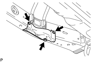
8. REMOVE REAR BUMPER SIDE SUPPORT LH
|
(a) Remove the 3 screws. |
|
(b) Detach the 5 claws to remove the rear bumper side support LH.
9. REMOVE REAR BUMPER SIDE SUPPORT RH
HINT:
Use the same procedure as for the LH side.
10. REMOVE REAR COMBINATION LIGHT LENS AND BODY LH
11. REMOVE REAR COMBINATION LIGHT LENS AND BODY RH
HINT:
Use the same procedure as for the LH side.
12. REMOVE REAR BUMPER UPPER RETAINER LH
|
(a) Detach the 2 clips to remove the rear bumper upper retainer LH. |
|
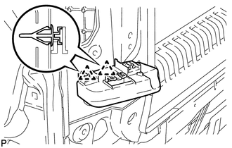
13. REMOVE REAR BUMPER UPPER RETAINER RH
HINT:
Use the same procedure as for the LH side.
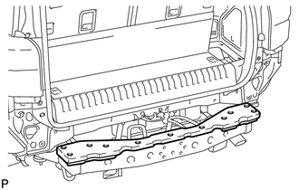
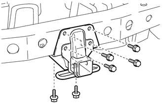
14. REMOVE PINTLE HOOK SUPPORT TUBE SUB-ASSEMBLY (w/ Pintle Hook)
|
(a) Remove the 6 bolts and pintle hook support tube sub-assembly. |
|
 Components
COMPONENTS
ILLUSTRATION
ILLUSTRATION
ILLUSTRATION
...
 Disassembly
DISASSEMBLY
PROCEDURE
1. REMOVE REAR BUMPER LOWER COVER (w/ Garnish)
(a) Remove the 2 clips and 14 outside moulding retainers.
(b) Detach the c ...
Other materials about Toyota 4Runner:
Cautions & Notices
CAUTION
This is a warning against something which, if ignored, may cause death or
serious injury to people. You are informed about what you must or must not do in
order to reduce the risk of death or serious injury to yourself and others.
NOTICE
This i ...
Data List / Active Test
DATA LIST / ACTIVE TEST
1. DATA LIST
HINT:
Using the Techstream to read the Data List allows the values or states of switches,
sensors, actuators and other items to be read without removing any parts. This non-intrusive
inspection can be very useful bec ...

0.011