Toyota 4Runner: Navigation Receiver
Components
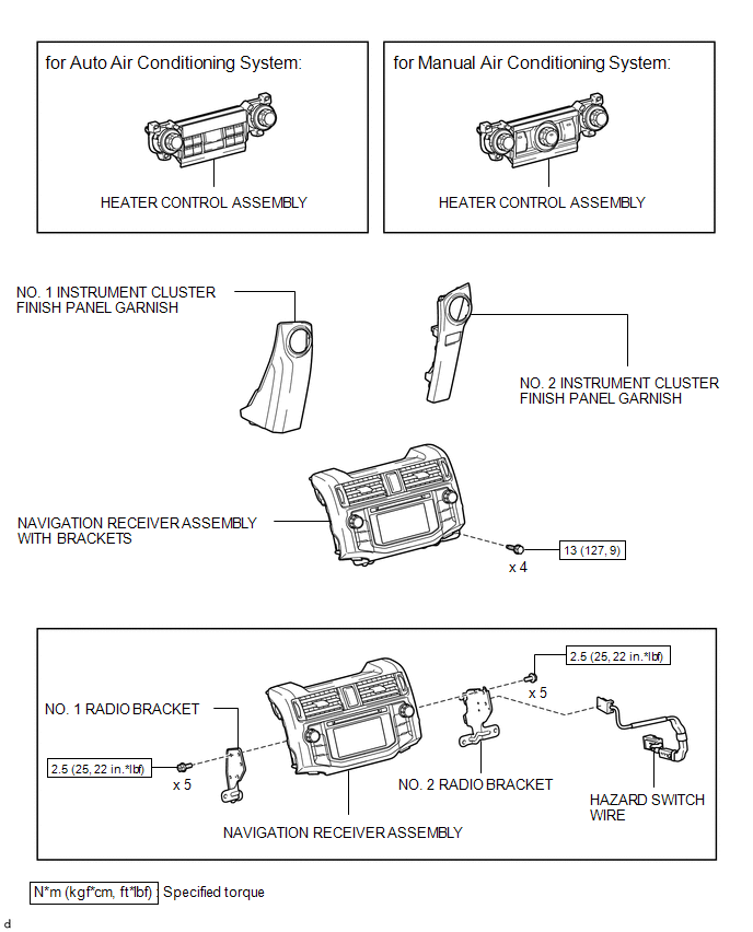
COMPONENTS
ILLUSTRATION
Removal
REMOVAL
PROCEDURE
1. DISCONNECT CABLE FROM NEGATIVE BATTERY TERMINAL
CAUTION:
Wait at least 90 seconds after disconnecting the cable from the negative (-) battery terminal to disable the SRS system.
NOTICE:
When disconnecting the cable, some systems need to be initialized after the cable
is reconnected (See page .gif) ).
).
2. REMOVE NO. 1 INSTRUMENT CLUSTER FINISH PANEL GARNISH
3. REMOVE NO. 2 INSTRUMENT CLUSTER FINISH PANEL GARNISH
4. REMOVE HEATER CONTROL ASSEMBLY
5. REMOVE NAVIGATION RECEIVER ASSEMBLY WITH BRACKETS
|
(a) Remove the 4 bolts. |
|
.png)
|
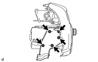
(b) Pull the navigation receiver assembly with brackets as shown in the illustration to detach the 6 claws on the backside of the navigation receiver assembly with brackets. |
|
.png)
(c) Disconnect each connector to remove the navigation receiver assembly with brackets.
6. REMOVE HAZARD SWITCH WIRE
|
(a) Detach the 2 clamps. |
|
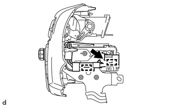
(b) Disconnect the connector to remove the hazard switch wire.
7. REMOVE NO. 1 RADIO BRACKET
|
(a) Remove the 5 screws and No. 1 radio bracket. |
|
8. REMOVE NO. 2 RADIO BRACKET
|
(a) Remove the 5 screws and No. 2 radio bracket. |
|
Installation
INSTALLATION
PROCEDURE
1. INSTALL NO. 2 RADIO BRACKET
(a) Install the No. 2 radio bracket with the 5 screws.
Torque:
2.5 N·m {25 kgf·cm, 22 in·lbf}
2. INSTALL NO. 1 RADIO BRACKET
(a) Install the No. 1 radio bracket with the 5 screws.
Torque:
2.5 N·m {25 kgf·cm, 22 in·lbf}
3. INSTALL HAZARD SWITCH WIRE
(a) Connect the connector.
(b) Attach the 2 clamps to install the hazard switch wire.
4. INSTALL NAVIGATION RECEIVER ASSEMBLY WITH BRACKETS
(a) Connect each connector.
|
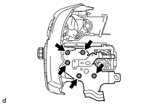
(b) Insert the navigation receiver assembly with brackets to attach the 6 claws on its backside. NOTICE: When inserting the navigation receiver assembly with brackets, do not press its knobs on it. |
|
.png)
(c) Install the navigation receiver assembly with brackets with the 4 bolts.
Torque:
13 N·m {127 kgf·cm, 9 ft·lbf}
5. INSTALL HEATER CONTROL ASSEMBLY
.gif)
6. INSTALL NO. 2 INSTRUMENT CLUSTER FINISH PANEL GARNISH
7. INSTALL NO. 1 INSTRUMENT CLUSTER FINISH PANEL GARNISH
8. CONNECT CABLE TO NEGATIVE BATTERY TERMINAL
NOTICE:
When disconnecting the cable, some systems need to be initialized after the cable
is reconnected (See page ).
9. CHECK SRS WARNING LIGHT
(See page )
 Installation
INSTALLATION
PROCEDURE
1. INSTALL NAVIGATION ANTENNA ASSEMBLY
(a) Install the antenna with the 2 screws.
Torque:
2.5 N·m {25 kgf·cm, 22 in·lbf}
(b) Attach the clamp.
2. INSTALL DEFROSTER NO ...

Other materials about Toyota 4Runner:
If your vehicle has to be stopped in an emergency
Only in an emergency, such as if it becomes impossible to stop the vehicle
in the normal way, stop the vehicle using the following procedure:
Steadily step on the brake pedal
with both feet and firmly depress it.
Do not pump the brake pedal repeatedly a ...
Registration
REGISTRATION
PROCEDURE
1. DESCRIPTION OF CODE REGISTRATION
HINT:
Recognition code registration is necessary when replacing door control
transmitter or door control receiver.
Add mode is used to register new recognition codes while still ret ...

0.0068