Toyota 4Runner: Radio Receiver Power Source Circuit
DESCRIPTION
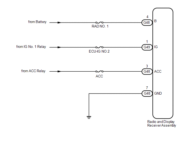
This is the power source circuit to operate the radio and display receiver assembly.
WIRING DIAGRAM
CAUTION / NOTICE / HINT
NOTICE:
Inspect the fuses for circuits related to this system before performing the following inspection procedure.
PROCEDURE
|
1. |
CHECK HARNESS AND CONNECTOR (RADIO AND DISPLAY RECEIVER ASSEMBLY - BATTERY, BODY GROUND) |
(a) Disconnect the G49 and G48 radio and display receiver assembly connectors.
(b) Measure the resistance according to the value(s) in the table below .
Standard Resistance:
|
Tester Connection |
Condition |
Specified Condition |
|---|---|---|
|
G48-7 (GND) - Body ground |
Always |
Below 1 Ω |
(c) Measure the voltage according to the value(s) in the table below.
Standard Voltage:
|
Tester Connection |
Condition |
Specified Condition |
|---|---|---|
|
G48-3 (ACC) - G48-7 (GND) |
Ignition switch ACC |
11 to 14 V |
|
G48-4 (B) - G48-7 (GND) |
Always |
11 to 14 V |
|
G49-1 (IG) - G48-7 (GND) |
Ignition switch ON |
11 to 14 V |
|
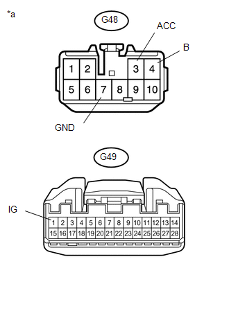
*a |
Front view of wire harness connector (to Radio and Display Receiver Assembly) |
| OK | .gif) |
PROCEED TO NEXT SUSPECTED AREA SHOWN IN PROBLEM SYMPTOMS TABLE |
| NG | |
REPAIR OR REPLACE HARNESS OR CONNECTOR |
 Microphone Circuit between Microphone and Radio Receiver
DESCRIPTION
The radio and display receiver assembly and map light assembly (telephone
microphone assembly) are connected to each other using the microphone connection
detection signal ...
 Back Door Speaker
Components
COMPONENTS
ILLUSTRATION
Removal
REMOVAL
CAUTION / NOTICE / HINT
HINT:
Use the same procedure for the RH and LH sides.
The procedure listed below is for the LH side. ...
Other materials about Toyota 4Runner:
Installation
INSTALLATION
PROCEDURE
1. INSTALL BACK DOOR OUTSIDE GARNISH (w/o Smart Key System)
(a) Attach the 3 clips to install the back door outside garnish.
(b) Install the 4 nuts.
(c) Connect the connector.
2. INSTALL BACK DOOR OUTSIDE GARNISH (w/ Smart Key Syst ...
Disassembly
DISASSEMBLY
PROCEDURE
1. REMOVE REAR BUMPER LOWER COVER (w/ Garnish)
(a) Remove the 2 clips and 14 outside moulding retainers.
(b) Detach the claw to remove the rear bumper lower cover
2. REMOVE REAR BU ...

0.0271