Toyota 4Runner: LVDS Signal Malfunction (from Extension Module) (B1532)
DESCRIPTION
|
DTC No. |
DTC Detection Condition |
Trouble Area |
|---|---|---|
|
B1532 |
When one of the conditions below is met:
|
|
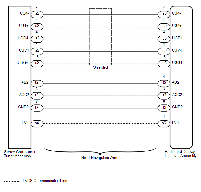
WIRING DIAGRAM
CAUTION / NOTICE / HINT
NOTICE:
After replacing the stereo component tuner assembly of vehicles subscribed to pay-type satellite radio broadcasts, XM radio ID registration is necessary (w/ SDARS System).
PROCEDURE
|
1. |
CHECK DTC |
(a) Clear the DTCs (See page .gif) ).
).
(b) Recheck for DTCs and check if the same DTC are output again.
OK:
No DTCs are output.
| OK | .gif) |
USE SIMULATION METHOD TO CHECK |
|
.gif)
|
2. |
CHECK HARNESS AND CONNECTOR (RADIO AND DISPLAY RECEIVER ASSEMBLY - STEREO COMPONENT TUNER ASSEMBLY) |
(a) Disconnect the s5 and t3 radio and display receiver assembly connectors.
(b) Disconnect the s2 and t2 stereo component tuner assembly connectors.
(c) Measure the resistance according to the value(s) in the table below.
Standard Resistance:
|
Tester Connection |
Condition |
Specified Condition |
|---|---|---|
|
s5-1 (USV4) - s2-1 (USV4) |
Always |
Below 1 Ω |
|
s5-2 (US4-) - s2-2 (US4-) |
Always |
Below 1 Ω |
|
s5-3 (US4+) - s2-3 (US4+) |
Always |
Below 1 Ω |
|
s5-4 (UGD4) - s2-4 (UGD4) |
Always |
Below 1 Ω |
|
s5-5 (USG4) - s2-5 (USG4) |
Always |
Below 1 Ω |
|
t3-4 (+B2) - t2-4 (+B2) |
Always |
Below 1 Ω |
|
t3-3 (ACC2) - t2-3 (ACC2) |
Always |
Below 1 Ω |
|
t3-8 (GND2) - t2-8 (GND2) |
Always |
Below 1 Ω |
|
s5-1 (USV4) - Body ground |
Always |
10 kΩ or higher |
|
s5-2 (US4-) - Body ground |
Always |
10 kΩ or higher |
|
s5-3 (US4+) - Body ground |
Always |
10 kΩ or higher |
|
s5-4 (UGD4) - Body ground |
Always |
10 kΩ or higher |
|
s5-5 (USG4) - Body ground |
Always |
10 kΩ or higher |
|
t3-4 (+B2) - Body ground |
Always |
10 kΩ or higher |
|
t3-3 (ACC2) - Body ground |
Always |
10 kΩ or higher |
|
t3-8 (GND2) - Body ground |
Always |
10 kΩ or higher |
| NG | |
REPAIR OR REPLACE HARNESS AND CONNECTOR |
|
|
3. |
REPLACE HARNESS AND CONNECTOR (LVDS COMMUNICATION LINE) |
(a) Replace the harness and connector (LVDS communication line).
(b) Clear the DTCs (See page ).
(c) Recheck for DTCs and check if the same DTC are output again.
OK:
No DTCs are output.
| OK | |
END |
|
|
4. |
REPLACE STEREO COMPONENT TUNER ASSEMBLY |
(a) Replace the stereo component tuner assembly (See page
).
(b) Clear the DTCs (See page ).
(c) Recheck for DTCs and check if the same DTC are output again.
OK:
No DTCs are output.
| OK | |
END |
| NG | |
REPLACE RADIO AND DISPLAY RECEIVER ASSEMBLY |
 Voice Recognition Microphone Disconnected (B1579)
DESCRIPTION
The radio and display receiver assembly and map light assembly (telephone microphone
assembly) are connected to each other using the microphone connection detection
signal lines.
Thi ...
 HD Radio Tuner Malfunction (B1551,B158D,B15A0,B15B0,B15B3,B15B4,B15B7)
DESCRIPTION
These DTCs are stored when a malfunction occurs in the radio and display receiver
assembly.
DTC No.
DTC Detection Condition
Trouble Area
...
Other materials about Toyota 4Runner:
Installation
INSTALLATION
PROCEDURE
1. INSTALL TRANSMISSION VALVE BODY ASSEMBLY
(a) Install the spring and check ball body.
(b) Insert the pin of the manual valve into the hole of the manual valve
lever.
Text in Illustration
*1
...
GPS Mark is not Displayed
CAUTION / NOTICE / HINT
NOTICE:
After replacing the navigation receiver assembly of vehicles subscribed to pay-type
satellite radio broadcasts, registration of the XM radio ID is necessary.
PROCEDURE
1.
CHECK CABIN
(a) Ch ...

0.0264