Toyota 4Runner: Occupant Classification Sensor Power Supply Circuit Malfunction (B1793)
DESCRIPTION
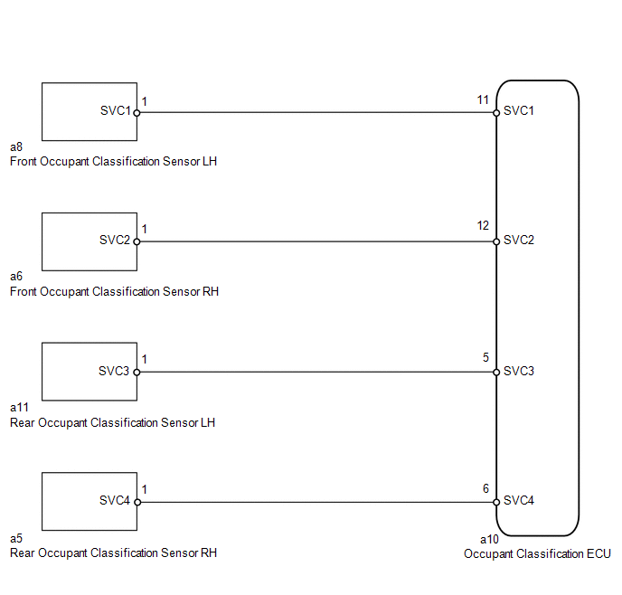
The occupant classification sensor power supply circuit consists of the occupant classification ECU and occupant classification sensors.
DTC B1793 is stored when a malfunction is detected in the occupant classification sensor power supply circuit.
|
DTC Code |
DTC Detection Condition |
Trouble Area |
|---|---|---|
|
B1793 |
One of the following conditions is met:
|
|
HINT:
- When DTC B1650/32 is stored as a result of troubleshooting the airbag system, perform troubleshooting for DTC B1793 of the occupant classification system.
- Use the Techstream to check for DTCs of the occupant classification ECU, otherwise the DTCs cannot be read.
WIRING DIAGRAM
CAUTION / NOTICE / HINT
HINT:
- If troubleshooting (wire harness inspection) is difficult to perform, remove the front seat RH installation bolts to see the undersurface of the seat cushion.
- In the above case, hold the seat so that it does not fall down. Holding the seat for a long period of time may cause problems, such as seat rail deformation. Hold the seat up only for as long as necessary.
PROCEDURE
|
1. |
CHECK FOR DTC |
(a) Turn the ignition switch to ON, and wait for at least 60 seconds.
(b) Clear the DTCs stored in memory (See page .gif)
).
HINT:
- First clear the DTCs stored in the occupant classification ECU, and then clear the DTCs stored in the center airbag sensor.
- Use the Techstream to clear the DTCs of the occupant classification ECU, otherwise the DTCs cannot be cleared.
(c) Turn the ignition switch off.
(d) Turn the ignition switch to ON, and wait for at least 60 seconds.
(e) Using the Techstream, check for DTCs of the occupant classification ECU (See
page ).
OK:
DTC B1793 is not output.
HINT:
DTCs other than DTC B1793 may be output at this time, but they are not related to this check.
| OK | .gif) |
USE SIMULATION METHOD TO CHECK |
|
.gif)
|
2. |
CHECK CONNECTION OF CONNECTOR |
(a) Turn the ignition switch off.
(b) Disconnect the cable from the negative (-) battery terminal, and wait for at least 90 seconds.
(c) Check that the connectors are properly connected to the occupant classification ECU and occupant classification sensors.
OK:
Connectors are properly connected.
| NG | |
CONNECT CONNECTOR |
|
|
3. |
CHECK CONNECTOR |
(a) Disconnect the connectors from the occupant classification ECU and 4 occupant classification sensors.
(b) Check that the connectors (on the occupant classification ECU side and occupant
classification sensor side) are not damaged (See page
).
OK:
Connectors are not deformed or damaged.
| NG | |
REPLACE FRONT SEAT WIRE RH |
|
|
4. |
CHECK FRONT SEAT WIRE RH |
(a) Connect the cable to the negative (-) battery terminal, and wait for at least 2 seconds.
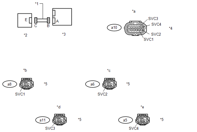 Text in Illustration
|
*1 |
Front Seat Wire RH |
*2 |
Occupant Classification Sensor |
|
*3 |
Occupant Classification ECU |
*4 |
Connector B |
|
*5 |
Connector C |
- |
- |
|
*a |
Front view of wire harness connector (to Occupant Classification ECU) |
*b |
Front view of wire harness connector (to Front Occupant Classification Sensor LH) |
|
*c |
Front view of wire harness connector (to Front Occupant Classification Sensor RH) |
*d |
Front view of wire harness connector (to Rear Occupant Classification Sensor LH) |
|
*e |
Front view of wire harness connector (to Rear Occupant Classification Sensor RH) |
- |
- |
(b) Measure the voltage according to the value(s) in the table below.
Standard Voltage:
|
Tester Connection |
Switch Condition |
Specified Condition |
|---|---|---|
|
a10-11 (SVC1) - Body ground |
Ignition switch ON |
Below 1 V |
|
a10-12 (SVC2) - Body ground |
||
|
a10-5 (SVC3) - Body ground |
||
|
a10-6 (SVC4) - Body ground |
(c) Turn the ignition switch off.
(d) Disconnect the cable from the negative (-) battery terminal, and wait for at least 90 seconds.
(e) Measure the resistance according to the value(s) in the table below.
Standard Resistance:
|
Tester Connection |
Condition |
Specified Condition |
|---|---|---|
|
a10-11 (SVC1) - a8-1 (SVC1) |
Always |
Below 1 Ω |
|
a10-12 (SVC2) - a6-1 (SVC2) |
||
|
a10-5 (SVC3) - a11-1 (SVC3) |
||
|
a10-6 (SVC4) - a5-1 (SVC4) |
||
|
a10-11 (SVC1) - a10-12 (SVC2) |
Always |
1 MΩ or higher |
|
a10-11 (SVC1) - a10-5 (SVC3) |
||
|
a10-11 (SVC1) - a10-6 (SVC4) |
||
|
a10-12 (SVC2) - a10-5 (SVC3) |
||
|
a10-12 (SVC2) - a10-6 (SVC4) |
||
|
a10-5 (SVC3) - a10-6 (SVC4) |
||
|
a10-11 (SVC1) - Body ground |
||
|
a10-12 (SVC2) - Body ground |
||
|
a10-5 (SVC3) - Body ground |
||
|
a10-6 (SVC4) - Body ground |
| NG | |
REPLACE FRONT SEAT WIRE RH |
|
|
5. |
CHECK FOR DTC |
(a) Connect the connectors to occupant classification ECU and 4 occupant classification sensors.
(b) Connect the cable to the negative (-) battery terminal, and wait for at least 2 seconds.
(c) Turn the ignition switch to ON, and wait for at least 60 seconds.
(d) Clear the DTCs stored in memory (See page
).
HINT:
- First clear the DTCs stored in the occupant classification ECU, and then clear the DTCs stored in the center airbag sensor.
- Use the Techstream to clear the DTCs of the occupant classification ECU, otherwise the DTCs cannot be cleared.
(e) Turn the ignition switch off.
(f) Turn the ignition switch to ON, and wait for at least 60 seconds.
(g) Using the Techstream, check for DTCs of the occupant classification ECU (See
page ).
OK:
DTC B1793 is not output.
HINT:
DTCs other than DTC B1793 may be output at this time, but they are not related to this check.
| OK | |
USE SIMULATION METHOD TO CHECK |
|
|
6. |
REPLACE OCCUPANT CLASSIFICATION ECU |
(a) Turn the ignition switch off.
(b) Disconnect the cable from the negative (-) battery terminal, and wait for at least 90 seconds.
(c) Replace the occupant classification ECU (See page
).
HINT:
Perform the inspection using parts from a normal vehicle when possible.
|
|
7. |
PERFORM ZERO POINT CALIBRATION |
(a) Connect the cable to the negative (-) battery terminal, and wait for at least 2 seconds.
(b) Turn the ignition switch to ON, and wait for at least 60 seconds.
(c) Using the Techstream, perform the zero point calibration (See page
).
OK:
"Zero Point Calibration is complete." is displayed.
| NG | |
GO TO STEP 10 |
|
|
8. |
PERFORM SENSITIVITY CHECK |
(a) Using the Techstream, perform the sensitivity check (See page
).
Standard range:
27 to 33 kg (59.5 to 72.8 lb)
| NG | |
GO TO STEP 10 |
|
|
9. |
CHECK FOR DTC |
(a) Clear the DTCs stored in memory (See page
).
HINT:
- First clear the DTCs stored in the occupant classification ECU, and then clear the DTCs stored in the center airbag sensor.
- Use the Techstream to clear the DTCs of the occupant classification ECU, otherwise the DTCs cannot be cleared.
(b) Turn the ignition switch off.
(c) Turn the ignition switch to ON, and wait for at least 60 seconds.
(d) Using the Techstream, check for DTCs of the occupant classification ECU (See
page ).
OK:
DTC B1793 is not output.
HINT:
DTCs other than DTC B1793 may be output at this time, but they are not related to this check.
| OK | |
END |
|
|
10. |
REPLACE SEPARATE TYPE FRONT SEAT CUSHION SPRING ASSEMBLY |
(a) Turn the ignition switch off.
(b) Disconnect the cable from the negative (-) battery terminal, and wait for at least 90 seconds.
(c) for Manual Seat:
(1) Replace the separate type front seat cushion spring RH (See page
).
(d) for Power Seat:
(1) Replace the separate type front seat cushion spring RH (See page
).
HINT:
Perform the inspection using parts from a normal vehicle when possible.
|
|
11. |
PERFORM ZERO POINT CALIBRATION |
(a) Connect the cable to the negative (-) battery terminal, and wait for at least 2 seconds.
(b) Turn the ignition switch to ON, and wait for at least 60 seconds.
(c) Using the Techstream, perform the zero point calibration (See page
).
OK:
"Zero Point Calibration is complete." is displayed.
|
|
12. |
PERFORM SENSITIVITY CHECK |
(a) Using the Techstream, perform the sensitivity check (See page
).
Standard range:
27 to 33 kg (59.5 to 72.8 lb)
| NEXT | |
END |
 Diagnostic Trouble Code Chart
DIAGNOSTIC TROUBLE CODE CHART
HINT:
When DTC B1650/32 is stored as a result of troubleshooting for the airbag
system, perform troubleshooting for the occupant classification system as
...
 Open in Occupant Classification ECU Battery Positive Line (B1794)
DESCRIPTION
DTC B1794 is stored when a malfunction is detected in the occupant classification
ECU.
DTC Code
DTC Detection Condition
Trouble Area
B ...
Other materials about Toyota 4Runner:
Rear Washer does not Operate
DESCRIPTION
The windshield wiper switch controls the rear washer motor and pump.
WIRING DIAGRAM
CAUTION / NOTICE / HINT
NOTICE:
Inspect the fuses for circuits related to this system before performing the following
inspection procedure.
PROCEDURE
...
Installation
INSTALLATION
PROCEDURE
1. INSTALL INDOOR NO. 2 ELECTRICAL KEY ANTENNA ASSEMBLY
(a) Attach the 2 claws to install the indoor No. 2 electrical key antenna.
(b) Connect the connector.
(c) Install the front ...

0.0075