Toyota 4Runner: On-vehicle Inspection
ON-VEHICLE INSPECTION
PROCEDURE
1. INSPECT DRIVE BELT
(a) Visually check the belt for excessive wear, frayed cords, etc.
If any defect is found, replace the drive belt.
HINT:
Cracks on the rib side of a belt are considered acceptable. Replace the belt if there are any missing ribs.
2. BLEED AIR FROM POWER STEERING SYSTEM
(a) Check the fluid level.
(b) Jack up the front of the vehicle and support it with stands.
(c) Turn the steering wheel.
(1) With the engine stopped, turn the wheel slowly from lock to lock several times.
(d) Lower the vehicle.
(e) Start the engine.
(1) Run the engine at idle for a few minutes.
(f) Turn the steering wheel.
(1) With the engine idling, turn the wheel to the left or right full lock position and keep it there for 2 to 3 seconds, and then turn the wheel to the opposite full lock position and keep it there for 2 to 3 seconds.*1
(2) Repeat *1 several times.
(g) Stop the engine.
|
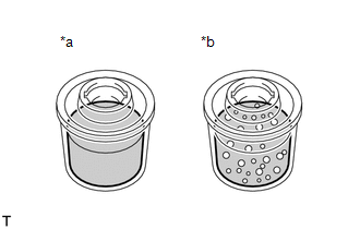
(h) Check for foaming or emulsification. Text in Illustration
If the system has to be bled twice specifically because of foaming or emulsification, check for fluid leaks in the power steering system. |
|
(i) Check the fluid level.
3. CHECK POWER STEERING FLUID LEVEL
|
(a) Keep the vehicle horizontal. |
|
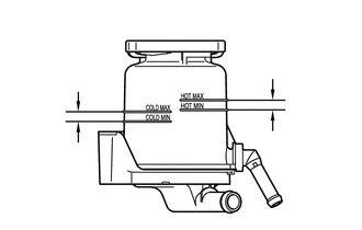
(b) With the engine stopped, check the fluid level in the reservoir.
If necessary, add fluid.
Fluid:
ATF "DEXRON" II or III, or equivalent
HINT:
If the fluid is hot (over 40°C (104°F)), make sure that the fluid level is within the HOT range on the reservoir. If the fluid is cold, make sure that it is within the COLD range.
(c) Start the engine and run it at idle.
(d) Turn the steering wheel from lock to lock several times to raise the fluid temperature.
Fluid temperature:
80°C (176°F)
|
(e) Check for foaming or emulsification. Text in Illustration
If foaming or emulsification is identified, bleed air from the power steering system. |
|
|
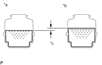
(f) With the engine idling, measure the fluid level in the reservoir. Text in Illustration
|
|
(g) Stop the engine.
(h) Wait a few minutes and remeasure the fluid level in the reservoir.
Maximum fluid level rise:
5.0 mm (0.197 in.)
If the fluid level rise is more than the maximum, bleed air from the power steering system.
(i) Check the fluid level.
4. CHECK STEERING FLUID PRESSURE
(a) Disconnect the pressure feed tube from the vane pump.
|
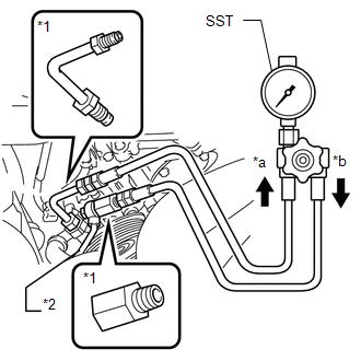
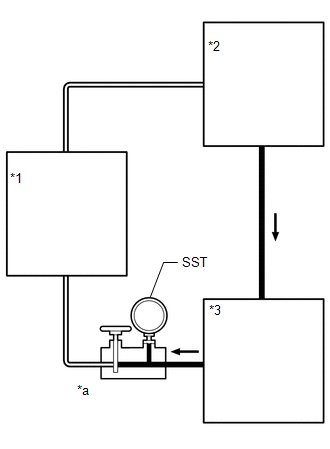
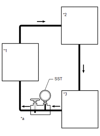
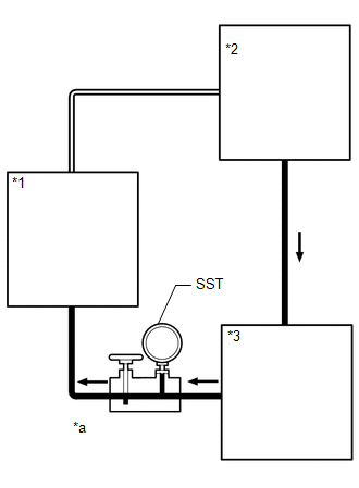
(b) Connect SST as shown in the illustration below. SST: 09950-60010 09951-00280 SST: 09950-70010 09951-07100 Text in Illustration
NOTICE: Check that the valve of SST is in the open position. |
|
(c) Bleed air from the power steering system.
(d) Start the engine and run it at idle.
(e) Turn the steering wheel from lock to lock several times to raise the fluid temperature.
Fluid temperature:
80°C (176°F)
|
(f) With the engine idling, close the valve of SST and observe the reading on SST. Standard fluid pressure: 8300 to 8800 kPa (84.7 to 89.7 kgf/cm2, 1204 to 1276 psi) Text in Illustration
NOTICE:
If the pressure is not within the specified range, check for fluid leaks and replace parts as necessary. |
|
|
(g) With the engine idling, open the valve fully. Text in Illustration
|
|
(h) Measure the fluid pressure at engine speeds of 1000 rpm and 3000 rpm.
Fluid pressure difference :
490 kPa (5.0 kgf/cm2, 71 psi) or less
NOTICE:
Do not turn the steering wheel.
If the pressure difference is above the specified range, check for fluid leaks and replace parts as necessary.
|
(i) With the engine idling and the valve fully open, turn the steering wheel left or right to the full lock position. Observe the reading on SST. Standard fluid pressure: 8300 to 8800 kPa (84.7 to 89.7 kgf/cm2, 1204 to 1276 psi) Text in Illustration
NOTICE:
If the pressure is not within the specified range, check for fluid leaks and replace parts as necessary. |
|
(j) Disconnect SST.
(k) Connect the pressure feed tube to the vane pump.
(l) Bleed air from the power steering system.
 Components
COMPONENTS
ILLUSTRATION
ILLUSTRATION
ILLUSTRATION
...
 Removal
REMOVAL
CAUTION / NOTICE / HINT
NOTICE:
When using a vise, do not overtighten it.
When installing the parts indicated by arrows, coat them with power
steering fluid (See page ).
...
Other materials about Toyota 4Runner:
No Signal from Transmitter ID1 in Main Mode (C2121/21-C2125/25,C2181/81-C2185/85)
DESCRIPTION
The tire pressure warning valve and transmitters that are installed in the tire
and wheel assemblies measure the tire pressure of the tires. The measured values
are transmitted to the tire pressure warning antenna and receiver on the body as
...
Tire inflation pressure
Tire inflation pressure
The recommended cold tire inflation pressure and tire size are displayed on
the tire and loading information label.
Inspection and adjustment procedure
1. Tire valve 2. Tire pressure gauge
Remove the tire valve cap.
Press t ...
0.0265

