Toyota 4Runner: Back Door ECU Communication Stop (B1287)
DESCRIPTION
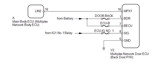
This DTC is stored when LIN communication between the multiplex network door ECU (back door P/W) and main body ECU (multiplex network body ECU) stops for 10 seconds or more.
|
DTC Code |
DTC Detection Condition |
Trouble Area |
|---|---|---|
|
B1287 |
No communication between the multiplex network door ECU (back door P/W) and main body ECU (multiplex network body ECU) for 10 seconds or more. |
|
WIRING DIAGRAM
CAUTION / NOTICE / HINT
NOTICE:
- When using the Techstream with the ignition switch off to troubleshoot:
Connect the Techstream to the vehicle and turn a courtesy light switch on and off at 1.5 second intervals until communication between the Techstream and vehicle begins.
- Inspect the fuses and bulbs for circuits related to this system before performing the following inspection procedure.
HINT:
When communication between the multiplex network door ECU (back door P/W) and main body ECU (multiplex network body ECU) stops, DTC B2325 is also stored.
PROCEDURE
|
1. |
CLEAR DTC |
(a) Clear the DTCs (See page .gif) ).
).
|
.gif)
|
2. |
CHECK FOR DTC |
(a) Check for DTCs (See page ).
OK:
DTC B1287 is not output.
| OK | .gif) |
USE SIMULATION METHOD TO CHECK |
|
|
3. |
CHECK HARNESS AND CONNECTOR (MAIN BODY ECU - MULTIPLEX NETWORK DOOR ECU) |
(a) Remove the main body ECU (multiplex network body ECU) from the driver side
junction block assembly (See page ).
(b) Disconnect the V2 multiplex network door ECU (back door P/W) connector.
(c) Measure the resistance according to the value(s) in the table below.
Standard Resistance:
|
Tester Connection |
Condition |
Specified Condition |
|---|---|---|
|
A-16 (LIN2) - V2-16 (MPX1) |
Always |
Below 1 Ω |
|
A-16 (LIN2) or V2-16 (MPX1) - Body ground |
Always |
10 kΩ or higher |
| NG | |
REPAIR OR REPLACE HARNESS OR CONNECTOR |
|
|
4. |
CHECK HARNESS AND CONNECTOR (MULTIPLEX NETWORK DOOR ECU - BATTERY AND BODY GROUND) |
|
(a) Disconnect the V2 multiplex network door ECU (back door P/W) connector. |
|
(b) Measure the resistance according to the value(s) in the table below.
Standard Resistance:
|
Tester Connection |
Condition |
Specified Condition |
|---|---|---|
|
V2-6 (GND) - Body ground |
Always |
Below 1 Ω |
(c) Measure the voltage according to the value(s) in the table below.
Standard Voltage:
|
Tester Connection |
Switch Condition |
Specified Condition |
|---|---|---|
|
V2-1 (BDR) - Body ground |
Always |
11 to 14 V |
|
V2-7 (BECU) - Body ground |
Always |
11 to 14 V |
|
V2-8 (SIG) - Body ground |
Ignition switch ON |
11 to 14 V |
|
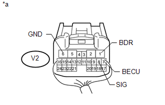
*a |
Rear view of wire harness connector (to Multiplex Network Door ECU [Back Door P/W]) |
| NG | |
REPAIR OR REPLACE HARNESS OR CONNECTOR |
|
|
5. |
REPLACE MULTIPLEX NETWORK DOOR ECU |
(a) Temporarily replace the multiplex network door ECU (back door P/W) with a
new or normally functioning one (See page ).
|
|
6. |
CLEAR DTC |
(a) Clear the DTCs (See page ).
|
|
7. |
CHECK FOR DTC |
(a) Check for DTCs (See page ).
OK:
DTC B1287 is not output.
| OK | |
END (MULTIPLEX NETWORK DOOR ECU IS DEFECTIVE) |
| NG | |
REPLACE MAIN BODY ECU (MULTIPLEX NETWORK BODY ECU) |
 LIN Communication Master Malfunction (B2287,B278C)
DESCRIPTION
DTC B2287 is stored when there is an open or short circuit or an ECU
communication malfunction between the power management control ECU and certification
ECU.
DTC B278C ...
 LIN Communication Bus Malfunction (B2325)
DESCRIPTION
The main body ECU (multiplex network body ECU) intermittently monitors the LIN
communication bus between the components related to the doors and sliding roof ECU
(sliding roof drive g ...
Other materials about Toyota 4Runner:
Vehicle Lift And Support Locations
VEHICLE LIFT AND SUPPORT LOCATIONS
1. NOTICE ABOUT VEHICLE CONDITION WHEN RAISING VEHICLE
(a) The vehicle must be unloaded before jacking up or raising the vehicle. Never
jack up or raise a heavily loaded vehicle.
(b) When removing any heavy components li ...
How To Proceed With Troubleshooting
CAUTION / NOTICE / HINT
HINT:
The wireless door lock control system troubleshooting procedures are
based on the premise that the power door lock control system is operating
normally. Check the power door lock control system first before troub ...

0.0081