
Toyota 4Runner: Only Back Door cannot be Opened
DESCRIPTION
When the back door is unlock and the multiplex network door ECU (back door P/W) receives the ON signal from the back door opener switch, it sends the signal to the main body ECU (multiplex network body ECU) which then activates the back door lock motor.
WIRING DIAGRAM
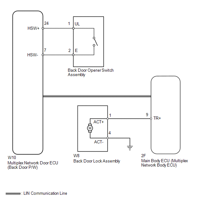
CAUTION / NOTICE / HINT
HINT:
Since the power door lock control system has functions that use LIN communication, first confirm that there is no malfunction in the communication system by inspecting the LIN communication functions in accordance with the "How to Proceed with Troubleshooting" procedures. Then, conduct the following inspection procedure.
PROCEDURE
|
1. |
READ VALUE USING TECHSTREAM (BACK DOOR OPENER SWITCH ASSEMBLY) |
(a) Use the Data List to check if the back door opener switch is functioning
properly (See page .gif) ).
).
Back Door P/W
|
Tester Display |
Measurement Item/Range |
Normal Condition |
Diagnostic Note |
|---|---|---|---|
|
Back Door Handle Switch |
Back door opener switch signal / ON or OFF |
ON: Back door opener switch pushed OFF: Back door opener switch not pushed |
- |
OK:
On tester screen, item changes between ON and OFF according to above chart.
| NG | .gif) |
GO TO STEP 6 |
|
.gif)
|
2. |
PERFORM ACTIVE TEST USING TECHSTREAM (BACK DOOR LOCK ASSEMBLY) |
(a) Select the Active Test and check that the back door lock operates (See page
).
Main Body
|
Tester Display |
Test Part |
Control Range |
Diagnostic Note |
|---|---|---|---|
|
Trunk and Back-Door Open |
Operate back door lock motor |
ON/OFF |
- |
OK:
The back door lock motor operates normally.
| NG | |
GO TO STEP 4 |
|
|
3. |
CHECK MULTIPLEX NETWORK DOOR ECU (BACK DOOR P/W) |
(a) Measure the voltage according to the value(s) in the table below.
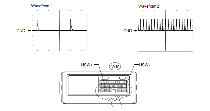
Standard Voltage:
|
Tester Connection |
Tool Setting |
Switch Condition |
Specified Condition |
|---|---|---|---|
|
W10-24 (HSW+) - W10-7 (HSW-) |
5 V/DIV., 10 ms/DIV. |
Back door opener switch off |
Pulse generation (See waveform 1 or 2) |
| OK | |
REPLACE MAIN BODY ECU (MULTIPLEX NETWORK BODY ECU) |
| NG | |
REPLACE MULTIPLEX NETWORK DOOR ECU (BACK DOOR P/W) |
|
4. |
INSPECT BACK DOOR LOCK ASSEMBLY |
(a) Set the back door lock to the full-latch position.
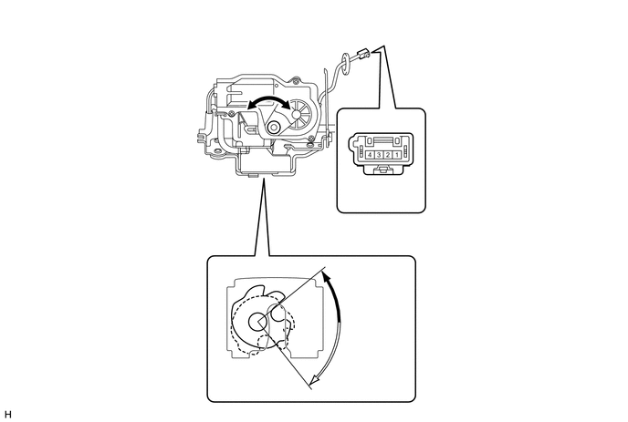
(b) Apply battery voltage to the door lock motor connector and check the operation of the door lock motor.
OK:
|
Measurement Condition |
Specified Condition |
|---|---|
|
Battery positive (+) → 1 (ACT+) Battery negative (-) → 4 (ACT-) |
Moves to open-latch position |
.png) |
Full-latch |
.png) |
Open-latch |
| NG | |
REPLACE BACK DOOR LOCK ASSEMBLY |
|
|
5. |
CHECK HARNESS AND CONNECTOR (BACK DOOR LOCK ASSEMBLY - MAIN BODY ECU AND BODY GROUND) |
(a) Disconnect the W8 back door lock connector.
(b) Disconnect the 2F main body ECU connector.
(c) Measure the voltage according to the value(s) in the table below.
Standard Resistance:
|
Tester Connection |
Condition |
Specified Condition |
|---|---|---|
|
W8-1 (ACT+) - 2F-9 (TR+) |
Always |
Below 1 Ω |
|
W8-4 (ACT-) - Body ground |
Always |
Below 1 Ω |
|
W8-1 (ACT+) - Body ground |
Always |
10 kΩ or higher |
| OK | |
REPLACE MAIN BODY ECU (MULTIPLEX NETWORK BODY ECU) |
| NG | |
REPAIR OR REPLACE HARNESS OR CONNECTOR |
|
6. |
INSPECT BACK DOOR OPENER SWITCH ASSEMBLY |
|
(a) Remove the back door opener switch (See page
|
|
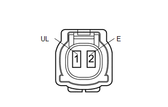
(b) Measure the resistance according to the value(s) in the table below.
Standard Resistance:
|
Tester Connection |
Switch Condition |
Specified Condition |
|---|---|---|
|
1 (UL) - 2 (E) |
Free |
10 kΩ or higher |
|
Pushed |
Below 1 Ω |
| NG | |
REPLACE BACK DOOR OPENER SWITCH ASSEMBLY |
|
|
7. |
CHECK HARNESS AND CONNECTOR (BACK DOOR OPENER SWITCH ASSEMBLY - MULTIPLEX NETWORK DOOR ECU) |
(a) Disconnect the back door opener switch connector.
(b) Disconnect the W10 multiplex network door ECU connector.
(c) Measure the resistance according to the value(s) in the table below.
Standard Resistance:
|
Tester Connection |
Condition |
Specified Condition |
|---|---|---|
|
W10-24 (HSW+) - W3-1 (UL) |
Always |
Below 1 Ω |
|
W10-7 (HSW-) - W3-2 (E) |
Always |
Below 1 Ω |
| OK | |
REPLACE MULTIPLEX NETWORK DOOR ECU (BACK DOOR P/W) |
| NG | |
REPAIR OR REPLACE HARNESS OR CONNECTOR |
 Data List / Active Test
DATA LIST / ACTIVE TEST
1. DATA LIST
HINT:
Using the Techstream to read the Data List allows the values or states of switches,
sensors, actuators and other items to be read without removing any p ...
 Rear Door Lock
...
Other materials about Toyota 4Runner:
Telephone Antenna
Components
COMPONENTS
ILLUSTRATION
Removal
REMOVAL
PROCEDURE
1. DISCONNECT CABLE FROM NEGATIVE BATTERY TERMINAL
NOTICE:
When disconnecting the cable, some systems need to be initialized after the cable
is reconnected (See page ).
2. REMOVE RO ...
How To Proceed With Troubleshooting
CAUTION / NOTICE / HINT
Use these procedures to troubleshoot the clock system.
PROCEDURE
1.
VEHICLE BROUGHT TO WORKSHOP
NEXT
2.
INSPECT ...

0.0081