Toyota 4Runner: Switch Failure (B2342)
DESCRIPTION
This DTC is stored when the sliding roof drive gear sub-assembly (sliding roof ECU) detects that the sliding roof switch in the map light assembly is stuck for 30 seconds or more.
|
DTC Code |
DTC Detection Condition |
Trouble Area |
|---|---|---|
|
B2342 |
Sliding roof drive gear sub-assembly detects that the sliding roof switch in the map light assembly is stuck for 30 seconds or more. |
|
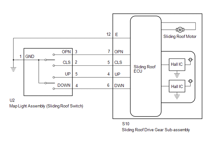
WIRING DIAGRAM
CAUTION / NOTICE / HINT
NOTICE:
When the sliding roof drive gear sub-assembly (sliding roof ECU) is removed and
reinstalled or replaced, the sliding roof drive gear sub-assembly (sliding roof
ECU) must be initialized (See page .gif) ).
).
PROCEDURE
|
1. |
CHECK FOR DTC |
(a) Clear the DTCs (See page ).
(b) Check for DTCs (See page ).
Result
|
Result |
Proceed to |
|---|---|
|
DTC B2342 is output |
A |
|
DTC is not output |
B |
| B | .gif) |
USE SIMULATION METHOD TO CHECK |
|
.gif)
|
2. |
READ VALUE USING TECHSTREAM (SLIDING ROOF) |
(a) Using the Techstream, read the Data List (See page
).
Sliding Roof
|
Tester Display |
Measurement Item/Range |
Normal Condition |
Diagnostic Note |
|---|---|---|---|
|
Open Switch Failure (Past) |
Slide open switch failure signal (Past) / ON or OFF |
ON: Slide open switch signal failure (Past) OFF: No slide open switch signal failure (Past) |
- |
|
Close Switch Failure (Past) |
Slide close switch failure signal (Past) / ON or OFF |
ON: Slide close switch signal failure (Past) OFF: No slide close switch signal failure (Past) |
- |
|
Up Switch Failure (Past) |
Tilt up switch failure signal (Past) / ON or OFF |
ON: Tilt up switch signal failure (Past) OFF: No tilt up switch signal failure (Past) |
- |
|
Down Switch Failure (Past) |
Tilt down switch failure signal (Past) / ON or OFF |
ON: Tilt down switch signal failure (Past) OFF: No tilt down switch signal failure (Past) |
- |
|
Open Switch Failure (Current) |
Slide open switch failure signal (Current) / ON or OFF |
ON: Slide open switch signal failure (Current) OFF: No slide open switch signal failure (Current) |
- |
|
Close Switch Failure (Current) |
Slide close switch failure signal (Current) / ON or OFF |
ON: Slide close switch signal failure (Current) OFF: No slide close switch signal failure (Current) |
- |
|
Up Switch Failure (Current) |
Tilt up switch failure signal (Current) / ON or OFF |
ON: Tilt up switch signal failure (Current) OFF: No tilt up switch signal failure (Current) |
- |
|
Down Switch Failure (Current) |
Tilt down switch failure signal (Current) / ON or OFF |
ON: Tilt down switch signal failure (Current) OFF: No tilt down switch signal failure (Current) |
- |
OK:
"OFF" appears on the Techstream screen.
| OK | |
REPLACE SLIDING ROOF DRIVE GEAR SUB-ASSEMBLY (SLIDING ROOF ECU) |
|
|
3. |
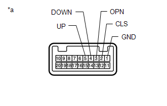
INSPECT MAP LIGHT ASSEMBLY (SLIDING ROOF SWITCH) |
|
*a |
Component without harness connected (Map Light Assembly (Sliding Roof Switch)) |
(a) Remove the map light assembly (sliding roof switch) (See page
).
(b) Measure the resistance according to the value(s) in the table below.
Standard Resistance:
|
Tester Connection |
Switch Condition |
Specified Condition |
|---|---|---|
|
5 (UP) - 1 (GND) |
Tilt up switch pressed |
Below 1 Ω |
|
5 (UP) - 1 (GND) |
Tilt up switch not pressed |
10 kΩ or higher |
|
4 (DOWN) - 1 (GND) |
Tilt down switch pressed |
Below 1 Ω |
|
4 (DOWN) - 1 (GND) |
Tilt down switch not pressed |
10 kΩ or higher |
|
3 (OPN) - 1 (GND) |
Slide open switch pressed |
Below 1 Ω |
|
3 (OPN) - 1 (GND) |
Slide open switch not pressed |
10 kΩ or higher |
|
2 (CLS) - 1 (GND) |
Slide close switch pressed |
Below 1 Ω |
|
2 (CLS) - 1 (GND) |
Slide close switch not pressed |
10 kΩ or higher |
| NG | |
REPLACE MAP LIGHT ASSEMBLY (SLIDING ROOF SWITCH) |
|
|
4. |
CHECK HARNESS AND CONNECTOR (SLIDING ROOF DRIVE GEAR SUB-ASSEMBLY (SLIDING ROOF ECU) - MAP LIGHT ASSEMBLY (SLIDING ROOF SWITCH) AND BODY GROUND) |
(a) Disconnect the S10 sliding roof drive gear sub-assembly (sliding roof ECU) connector.
(b) Disconnect the U2 map light assembly (sliding roof switch) connector.
(c) Measure the resistance according to the value(s) in the table below.
Standard Resistance:
|
Tester Connection |
Condition |
Specified Condition |
|---|---|---|
|
S10-4 (UP) - U2-5 (UP) |
Always |
Below 1 Ω |
|
S10-6 (DWN) - U2-4 (DOWN) |
Always |
Below 1 Ω |
|
S10-7 (OPN) - U2-3 (OPN) |
Always |
Below 1 Ω |
|
S10-5 (CLS) - U2-2 (CLS) |
Always |
Below 1 Ω |
|
U2-1 (GND) - Body ground |
Always |
Below 1 Ω |
|
S10-12 (E) - Body ground |
Always |
Below 1 Ω |
|
S10-4 (UP) or U2-5 (UP) - Body ground |
Always |
10 kΩ or higher |
|
S10-6 (DWN) or U2-4 (DOWN) - Body ground |
Always |
10 kΩ or higher |
|
S10-7 (OPN) or U2-3 (OPN) - Body ground |
Always |
10 kΩ or higher |
|
S10-5 (CLS) or U2-2 (CLS) - Body ground |
Always |
10 kΩ or higher |
| OK | |
REPLACE SLIDING ROOF DRIVE GEAR SUB-ASSEMBLY (SLIDING ROOF ECU) |
| NG | |
REPAIR OR REPLACE HARNESS OR CONNECTOR |
 Diagnostic Trouble Code Chart
DIAGNOSTIC TROUBLE CODE CHART
HINT:
If a trouble code is output during the DTC check, inspect the trouble areas listed
for that code. For details of the code, refer to the "See page" bel ...
 Position Initialization Incomplete (B2343)
DESCRIPTION
This DTC is stored when the sliding roof drive gear sub-assembly (sliding roof
ECU) has not been initialized.
DTC Code
DTC Detection Condition
Trouble ...
Other materials about Toyota 4Runner:
Shifting between H2 and H4
Shifting from H2 to H4
Type A
Reduce vehicle speed to less
than 50 mph (80 km/h).
Shift the front-wheel drive
control lever to H4.
Type B
Reduce vehicle speed to less
than 62 mph (100 km/h).
Push the “UNLOCK” button and
turn the front-whee ...
Removal
REMOVAL
PROCEDURE
1. REMOVE REAR NO. 1 SPOILER COVER
(a) Detach the 4 clips and remove the rear No. 1 spoiler cover.
2. REMOVE REAR SPOILER SUB-ASSEMBLY
(a) Remove the 4 grommets and 4 bolts.
...

0.0268