Toyota 4Runner: Open in CAN Main Wire
DESCRIPTION
There may be an open circuit in the CAN main wire and/or DLC3 branch wire when the resistance between terminals 6 (CANH) and 14 (CANL) of the DLC3 is 69 Ω or higher.
|
Symptom |
Trouble Area |
|---|---|
|
The resistance between terminals 6 (CANH) and 14 (CANL) of the DLC3 is 69 Ω or higher. |
|
*: for 4WD
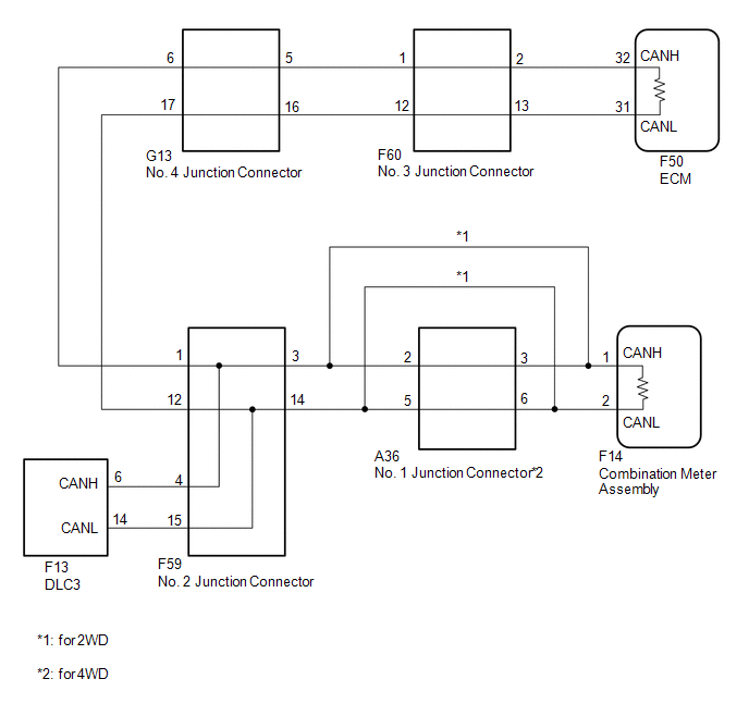
WIRING DIAGRAM
CAUTION / NOTICE / HINT
HINT:
Operating the ignition switch, any switches or any doors triggers related ECU and sensor communication with the CAN, which causes resistance variation.
PROCEDURE
|
1. |
DISCONNECT CABLE FROM NEGATIVE BATTERY TERMINAL |
(a) Disconnect the cable from the negative (-) battery terminal before measuring the resistances of the main wire and branch wire.
CAUTION:
Wait at least 90 seconds after disconnecting the cable from the negative (-) battery terminal to disable the SRS system.
NOTICE:
When disconnecting the cable, some systems need to be initialized after the cable
is reconnected (See page .gif) ).
).
|
.gif)
|
2. |
CHECK FOR OPEN IN CAN BUS WIRE (NO. 2 JUNCTION CONNECTOR - DLC3) |
|
(a) Disconnect the F59 No. 2 junction connector connector. |
|
(b) Measure the resistance according to the value(s) in the table below.
Standard Resistance:
|
Tester Connection |
Switch Condition |
Specified Condition |
|---|---|---|
|
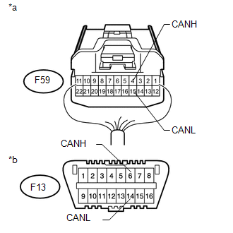
F59-4 (CANH) - F13-6 (CANH) |
Ignition switch off |
Below 1 Ω |
|
F59-15 (CANL) - F13-14 (CANL) |
Ignition switch off |
Below 1 Ω |
|
*a |
Rear view of wire harness connector (to No. 2 Junction Connector) |
|
*b |
Front view of DLC3 |
| NG | .gif) |
REPAIR OR REPLACE CAN BRANCH WIRE CONNECTED TO DLC3 (CANH, CANL) |
|
|
3. |
CHECK FOR OPEN IN CAN BUS MAIN WIRE (NO. 2 JUNCTION CONNECTOR - COMBINATION METER ASSEMBLY) |
|
(a) Measure the resistance according to the value(s) in the table below. Standard Resistance:
|
|
|
Result |
Proceed to |
|---|---|
|
OK |
A |
|
NG (for 2WD) |
B |
|
NG (for 4WD) |
C |
| B | |
GO TO STEP 5 |
| C | |
GO TO STEP 7 |
|
|
4. |
CHECK FOR OPEN IN CAN BUS MAIN WIRE (NO. 2 JUNCTION CONNECTOR - ECM) |
|
(a) Measure the resistance according to the value(s) in the table below. Standard Resistance:
|
|
| OK | |
REPAIR OR REPLACE NO. 2 JUNCTION CONNECTOR |
| NG | |
GO TO STEP 12 |
|
5. |
CONNECT CONNECTOR |
(a) Reconnect the F59 No. 2 junction connector connector.
|
|
6. |
CHECK FOR OPEN IN CAN BUS MAIN WIRE (COMBINATION METER ASSEMBLY - NO. 2 JUNCTION CONNECTOR) |
|
(a) Disconnect the F14 combination meter assembly connector. |
|
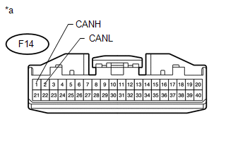
(b) Measure the resistance according to the value(s) in the table below.
Standard Resistance:
|
Tester Connection |
Switch Condition |
Specified Condition |
|---|---|---|
|
F14-1 (CANH) - F14-2 (CANL) |
Ignition switch off |
108 to 132 Ω |
|
*a |
Front view of wire harness connector (to Combination Meter Assembly) |
| OK | |
REPLACE COMBINATION METER ASSEMBLY |
| NG | |
REPAIR OR REPLACE CAN MAIN WIRE CONNECTED TO COMBINATION METER ASSEMBLY (COMBINATION METER ASSEMBLY - NO. 2 JUNCTION CONNECTOR) |
|
7. |
CONNECT CONNECTOR |
(a) Reconnect the F59 No. 2 junction connector connector.
|
|
8. |
CHECK FOR OPEN IN CAN BUS MAIN WIRE (NO. 1 JUNCTION CONNECTOR - COMBINATION METER ASSEMBLY) |
|
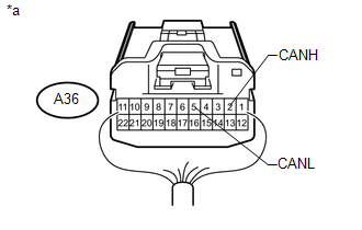
(a) Disconnect the A36 No. 1 junction connector connector. |
|
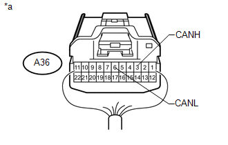
(b) Measure the resistance according to the value(s) in the table below.
Standard Resistance:
|
Tester Connection |
Switch Condition |
Specified Condition |
|---|---|---|
|
A36-3 (CANH) - A36-6 (CANL) |
Ignition switch off |
108 to 132 Ω |
|
*a |
Rear view of wire harness connector (to No. 1 Junction Connector) |
| NG | |
GO TO STEP 10 |
|
|
9. |
CHECK FOR OPEN IN CAN BUS MAIN WIRE (NO. 1 JUNCTION CONNECTOR - NO. 2 JUNCTION CONNECTOR) |
|
(a) Measure the resistance according to the value(s) in the table below. Standard Resistance:
|
|
| OK | |
REPAIR OR REPLACE NO. 1 JUNCTION CONNECTOR |
| NG | |
REPAIR OR REPLACE CAN MAIN WIRE OR CONNECTOR (NO. 1 JUNCTION CONNECTOR - NO. 2 JUNCTION CONNECTOR) |
|
10. |
CONNECT CONNECTOR |
(a) Reconnect the A36 No. 1 junction connector connector.
|
|
11. |
CHECK FOR OPEN IN CAN BUS MAIN WIRE (COMBINATION METER ASSEMBLY - NO. 1 JUNCTION CONNECTOR) |
|
(a) Disconnect the F14 combination meter assembly connector. |
|
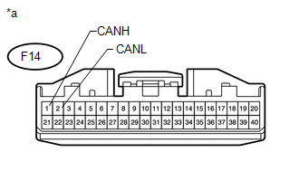
(b) Measure the resistance according to the value(s) in the table below.
Standard Resistance:
|
Tester Connection |
Switch Condition |
Specified Condition |
|---|---|---|
|
F14-1 (CANH) - F14-2 (CANL) |
Ignition switch off |
108 to 132 Ω |
|
*a |
Front view of wire harness connector (to Combination Meter Assembly) |
| OK | |
REPLACE COMBINATION METER ASSEMBLY |
| NG | |
REPAIR OR REPLACE CAN MAIN WIRE CONNECTED TO COMBINATION METER ASSEMBLY (COMBINATION METER ASSEMBLY - NO. 1 JUNCTION CONNECTOR) |
|
12. |
CONNECT CONNECTOR |
(a) Reconnect the F59 No. 2 junction connector connector.
|
|
13. |
CHECK FOR OPEN IN CAN BUS MAIN WIRE (NO. 4 JUNCTION CONNECTOR - ECM) |
|
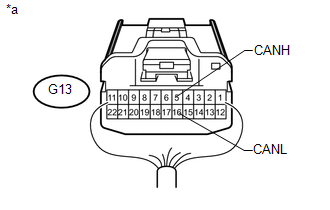
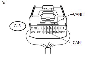
(a) Disconnect the G13 No. 4 junction connector connector. |
|
(b) Measure the resistance according to the value(s) in the table below.
Standard Resistance:
|
Tester Connection |
Switch Condition |
Specified Condition |
|---|---|---|
|
G13-5 (CANH) - G13-16 (CANL) |
Ignition switch off |
108 to 132 Ω |
|
*a |
Rear view of wire harness connector (to No. 4 Junction Connector) |
| NG | |
GO TO STEP 15 |
|
|
14. |
CHECK FOR OPEN IN CAN BUS MAIN WIRE (NO. 4 JUNCTION CONNECTOR - NO. 2 JUNCTION CONNECTOR) |
|
(a) Measure the resistance according to the value(s) in the table below. Standard Resistance:
|
|
| OK | |
REPAIR OR REPLACE NO. 4 JUNCTION CONNECTOR |
| NG | |
REPAIR OR REPLACE CAN MAIN WIRE OR CONNECTOR (NO. 4 JUNCTION CONNECTOR - NO. 2 JUNCTION CONNECTOR) |
|
15. |
CONNECT CONNECTOR |
(a) Reconnect the G13 No. 4 junction connector connector.
|
|
16. |
CHECK FOR OPEN IN CAN BUS MAIN WIRE (NO. 3 JUNCTION CONNECTOR - ECM) |
|
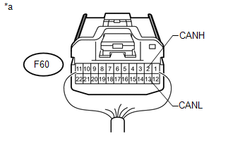
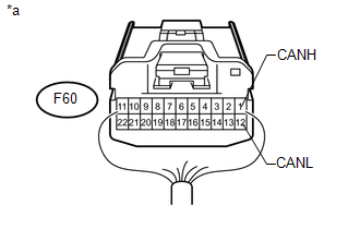
(a) Disconnect the F60 No. 3 junction connector connector. |
|
(b) Measure the resistance according to the value(s) in the table below.
Standard Resistance:
|
Tester Connection |
Switch Condition |
Specified Condition |
|---|---|---|
|
F60-2 (CANH) - F60-13 (CANL) |
Ignition switch off |
108 to 132 Ω |
|
*a |
Rear view of wire harness connector (to No. 3 Junction Connector) |
| NG | |
GO TO STEP 18 |
|
|
17. |
CHECK FOR OPEN IN CAN BUS MAIN WIRE (NO. 3 JUNCTION CONNECTOR - NO. 4 JUNCTION CONNECTOR) |
|
(a) Measure the resistance according to the value(s) in the table below. Standard Resistance:
|
|
| OK | |
REPAIR OR REPLACE NO. 3 JUNCTION CONNECTOR |
| NG | |
REPAIR OR REPLACE CAN MAIN WIRE OR CONNECTOR (NO. 3 JUNCTION CONNECTOR - NO. 4 JUNCTION CONNECTOR) |
|
18. |
CONNECT CONNECTOR |
(a) Reconnect the F60 No. 3 junction connector connector.
|
|
19. |
CHECK FOR OPEN IN CAN BUS MAIN WIRE (ECM - NO. 3 JUNCTION CONNECTOR) |
|
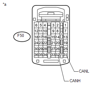
(a) Disconnect the F50 ECM connector. |
|
(b) Measure the resistance according to the value(s) in the table below.
Standard Resistance:
|
Tester Connection |
Switch Condition |
Specified Condition |
|---|---|---|
|
F50-32 (CANH) - F50-31 (CANL) |
Ignition switch off |
108 to 132 Ω |
|
*a |
Rear view of wire harness connector (to ECM) |
| OK | |
REPLACE ECM |
| NG | |
REPAIR OR REPLACE CAN MAIN WIRE CONNECTED TO ECM (ECM - NO. 3 JUNCTION CONNECTOR) |
 Audio Receiver Assembly Communication Stop Mode
DESCRIPTION
Detection Item
Symptom
Trouble Area
Audio Receiver Assembly Communication Stop Mode
Either condition is met:
&qu ...
 Short in CAN Bus Lines
DESCRIPTION
There may be a short circuit between the CAN bus lines when the resistance between
terminals 6 (CANH) and 14 (CANL) of the DLC3 is below 54 Ω.
Symptom
Trouble Ar ...
Other materials about Toyota 4Runner:
Installation
INSTALLATION
PROCEDURE
1. TEMPORARILY INSTALL FRONT STABILIZER LINK ASSEMBLY RH
(a) Temporarily install the front stabilizer link assembly with the bolt.
HINT:
Make sure that the identification mark on the front stabilizer link assembly
...
Installation
INSTALLATION
PROCEDURE
1. INSTALL WIRELESS DOOR LOCK BUZZER
(a) Connect the connector.
(b) Attach the clamp to install the wireless door lock buzzer.
2. INSTALL FRONT FENDER LINER LH (w/ Intuitive Parking Assist System)
(a) Install the front fender liner ...

0.0076