Toyota 4Runner: Open in Stop Light Switch Circuit (C1425)
DESCRIPTION
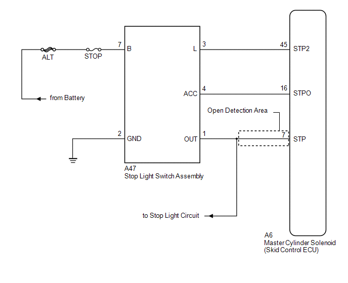
The skid control ECU receives the stop light switch assembly signal and detects the brake pedal operation status.
The skid control ECU has an open detection circuit, which stores this DTC if it detects an open in the stop light input line of the stop light circuit with the stop light switch assembly off (brake pedal not depressed).
|
DTC No. |
DTC Detection Condition |
Trouble Area |
|---|---|---|
|
C1425 |
When the IG1 terminal voltage is between 9.5 and 17.4 V and the skid control ECU STPO terminal output is off, an open in the stop light switch circuit continues for 3 seconds or more. |
|
WIRING DIAGRAM
CAUTION / NOTICE / HINT
NOTICE:
- When replacing the master cylinder solenoid (skid control ECU), perform
initialization and calibration of the linear solenoid valve (See page
.gif) ).
).
- Inspect the fuses for circuits related to this system before performing the following inspection procedure.
PROCEDURE
|
1. |
CHECK STOP LIGHT OPERATION |
(a) Check that the stop lights come on when the brake pedal is depressed, and go off when the brake pedal is released.
OK:
|
Condition |
Illumination Condition |
|---|---|
|
Brake pedal depressed. |
ON |
|
Brake pedal released. |
OFF |
| NG | .gif) |
GO TO STEP 4 |
|
.gif)
|
2. |
READ VALUE USING TECHSTREAM (STOP LIGHT SW) |
(a) Connect the Techstream to the DLC3.
(b) Turn the ignition switch to ON.
(c) Select the Data List on the Techstream (See page
).
ABS/VSC/TRAC
|
Tester Display |
Measurement Item/Range |
Normal Condition |
Diagnostic Note |
|---|---|---|---|
|
Stop Light SW |
Stop light switch assembly / ON or OFF |
ON: Brake pedal depressed OFF: Brake pedal released |
- |
(d) Check that the Stop Light SW display observed on the Techstream changes according to brake pedal operation.
OK:
The Techstream displays ON or OFF according to brake pedal operation.
| NG | |
GO TO STEP 7 |
|
|
3. |
RECONFIRM DTC |
(a) Turn the ignition switch off.
(b) Clear the DTCs (See page ).
(c) Turn the ignition switch to ON.
(d) Depress the brake pedal several times to test the stop light circuit.
(e) Check if the same DTC is output (See page
).
|
Result |
Proceed to |
|---|---|
|
DTC C1425 is not output. |
A |
|
DTC C1425 is output. |
B |
| A | |
CHECK FOR INTERMITTENT PROBLEMS |
| B | |
REPLACE MASTER CYLINDER SOLENOID |
|
4. |
CHECK STOP LIGHT SWITCH ASSEMBLY |
(a) Check the stop light switch assembly (See page
).
OK:
The stop light switch assembly is normal.
| NG | |
REPLACE STOP LIGHT SWITCH ASSEMBLY |
|
|
5. |
CHECK HARNESS AND CONNECTOR (STP TERMINAL) |
|
(a) Make sure that there is no looseness at the locking part and the connecting part of the connector. |
|
(b) Disconnect the A6 skid control ECU connector.
(c) Measure the voltage according to the value(s) in the table below.
Standard Voltage:
|
Tester Connection |
Condition |
Specified Condition |
|---|---|---|
|
A6-7 (STP) - Body ground |
Stop light switch assembly ON (Brake pedal depressed) |
11 to 14 V |
|
A6-7 (STP) - Body ground |
Stop light switch assembly OFF (Brake pedal released) |
Below 1.5 V |
|
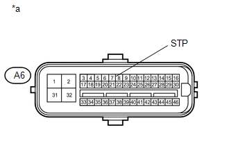
*a |
Front view of wire harness connector (to Skid Control ECU) |
| NG | |
REPAIR OR REPLACE HARNESS OR CONNECTOR (STP CIRCUIT) |
|
|
6. |
RECONFIRM DTC |
(a) Reconnect the A6 skid control ECU connector.
(b) Clear the DTCs (See page ).
(c) Turn the ignition switch to ON.
(d) Depress the brake pedal several times to test the stop light circuit.
(e) Check if the same DTC is output (See page
).
|
Result |
Proceed to |
|---|---|
|
DTC C1425 is not output. |
A |
|
DTC C1425 is output. |
B |
HINT:
If the lighting system is normal but the DTC is still output, replace the master
cylinder solenoid (skid control ECU) (See page
).
| A | |
CHECK FOR INTERMITTENT PROBLEMS |
| B | |
INSPECT LIGHTING SYSTEM (STOP LIGHT CIRCUIT) |
|
7. |
CHECK HARNESS AND CONNECTOR (STP TERMINAL) |
|
(a) Turn the ignition switch off. |
|
(b) Make sure that there is no looseness at the locking part and the connecting part of the connector.
(c) Disconnect the A6 skid control ECU connector.
(d) Measure the voltage according to the value(s) in the table below.
Standard Voltage:
|
Tester Connection |
Condition |
Specified Condition |
|---|---|---|
|
A6-7 (STP) - Body ground |
Stop light switch assembly ON (Brake pedal depressed) |
11 to 14 V |
|
A6-7 (STP) - Body ground |
Stop light switch assembly OFF (Brake pedal released) |
Below 1.5 V |
|
*a |
Front view of wire harness connector (to Skid Control ECU) |
| OK | |
REPLACE MASTER CYLINDER SOLENOID |
| NG | |
REPAIR OR REPLACE HARNESS OR CONNECTOR (STP CIRCUIT) |
 Master Cylinder Pressure Sensor Zero Point High Malfunction (C1422)
DESCRIPTION
Refer to DTCs C1421, C1423 and C1424 (See page
).
DTC Code
DTC Detection Condition
Trouble Area
C1422
When the stop light s ...
 Steering Angle Sensor Power Source Voltage Malfunction (C1432)
DESCRIPTION
Steering angle sensor signals are sent to the skid control ECU via the CAN communication
system. When there is a malfunction in the CAN communication system, it is detected
by the ste ...
Other materials about Toyota 4Runner:
Registered Device cannot be Deleted
PROCEDURE
1.
DELETE OPERATION
(a) Check if a registered portable player can be deleted normally.
OK:
Registered portable player can be deleted normally.
OK
USE SIMULATION METHOD TO CHECK
...
Using the interior lights
Interior lights list
1. Rear interior light
2. Front interior light/front personal lights
3. Shift lever light (when the engine switch is in the “ACC” or “ON” position
[without a smart key system] or “ENGINE START STOP” switch is in ACCESS ...

0.0155