Toyota 4Runner: Operation Check
OPERATION CHECK
1. CHECK INITIAL CHECK FUNCTION
(a) Check the initial check function for the buzzer.
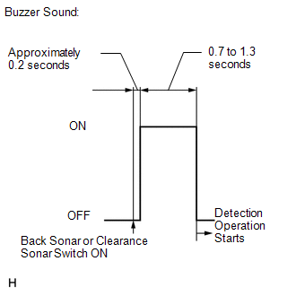
(1) When the back sonar or clearance sonar switch assembly is turned on, check that the following occurs: 1) after 0.2 seconds, the buzzer sounds for approximately 0.7 to 1.3 seconds, and 2) the system starts the obstacle detection operation.
(b) Check the initial check function for the sensor.
- Approximately 0.2 seconds after the ignition switch is turned to ON and the back sonar or clearance sonar switch is turned on, all the sensors are checked by the system.
- When the shift lever is operated, the system starts the obstacle detection operation.
2. MALFUNCTION DISPLAY (MULTI-INFORMATION DISPLAY)
(a) Open circuit indication
(1) If there is an open circuit between the ultrasonic sensor and the clearance warning ECU assembly or a sensor is malfunctioning, the malfunction is displayed as shown in the illustration.
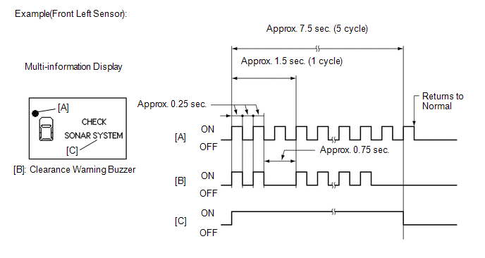
HINT:
The example shows an open circuit in the ultrasonic sensor (front left sensor).
(b) Frozen indication
(1) If a sensor is covered with foreign matter, such as mud or snow, the affected sensor is displayed as shown in the illustration.
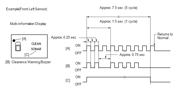
HINT:
- The example shows that the ultrasonic sensor (front left sensor) is covered with foreign matter.
- If "CLEAN SONAR" is displayed, refer to "Frozen indication is displayed
in self-check function" on Problem Symptoms Table to inspect it (See page
.gif) ).
).
3. DETECTION RANGE MEASUREMENT AND DISPLAY INSPECTION
(a) Detection range measurement:
NOTICE:
Make sure that the vehicle does not move by applying the parking brake firmly.
(1) Turn the ignition switch to ON.
(2) Move the shift lever to R to check the ultrasonic sensors.
(b) Turn the clearance sonar main switch on.
(c) Move a 60 mm (2.36 in.) diameter pole near each sensor to measure its detection range.
NOTICE:
These detection ranges are applicable when positioning the 60 mm (2.36 in.) diameter pole parallel or perpendicular to the ground. The detection range varies depending on the measuring method and type of obstacle (such as walls).
HINT:
Have an assistant move the pole.
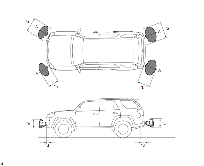
(1) Clearance Sonar
 Text in Illustration
|
*a |
Approx. 950 mm (37.4 in.) |
*b |
Approx. 600 mm (23.6 in.) |
|
*c |
Approx. 500 mm (19.7 in.) |
*d |
Approx. 200 mm (7.9 in.) |
 |
Hatched Area |
- |
- |
NOTICE:
The No. 1 ultrasonic sensor side view detection range hatched area (labeled *1) represents the cross section of the top view of the lines of detection range A. The hatched area *1 does not represent the entire side view detection range.
(2) Back Sonar
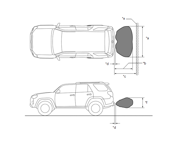 Text in Illustration
|
*a |
Approx. 1800 mm (70.9 in.) |
*b |
Approx. 1350 mm (53.1 in.) |
|
*c |
Approx. 1500 mm (59.1 in.) |
*d |
Approx. 200 mm (7.9 in.) |
|
*e |
Wall |
*f |
Approx. 600 mm (23.6 in.) |
|
|
Hatched Area |
- |
- |
(d) When the ultrasonic sensors (front corner sonar) have detected an obstacle, check the displays and check that the buzzer sounds.
Operation Condition|
Ignition Switch |
Clearance Sonar Main Switch |
Shift Lever Position |
Vehicle Speed |
|---|---|---|---|
|
ON |
On |
In any position other than P |
|
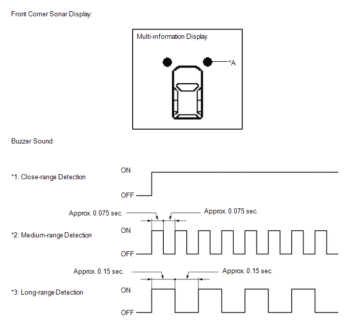
Standard:
Multi-information Display and Buzzer|
Detection Range |
During Judgment |
Obstacle |
|---|---|---|
|
*1 Close-range detection Within approx. 300 +/- 30 mm (11.8 +/- 1.2 in.) |
Buzzer: Sounds continuously |
60 mm (2.36 in.) diameter pole |
|
*2 Medium-range detection From approx. 300 +/- 30 to 450 +/- 50 mm (11.8 +/- 1.2 to 15.7 +/- 1.6 in.) |
Buzzer: Sounds intermittently (ON: 0.075 sec. / OFF: 0.075 sec.) |
60 mm (2.36 in.) diameter pole |
|
*3 Long-range detection From approx. 450+/- 50 to 600 +/- 60 mm (17.7 +/- 2.0 to 23.6 +/- 2.4 in.) |
Buzzer: Sounds intermittently (ON: 0.15 sec. / OFF: 0.15 sec.) |
60 mm (2.36 in.) diameter pole |
HINT:
Ultrasonic waves are used to measure the detection range; however, the detection range may vary depending on the ambient temperature.
(e) When the ultrasonic sensors (rear corner sonar) have detected an obstacle, check the displays and check that the buzzer sounds.
Operation Condition|
Ignition Switch |
Clearance Sonar Main Switch |
Shift Lever Position |
Vehicle Speed |
|---|---|---|---|
|
ON |
On |
R |
- |
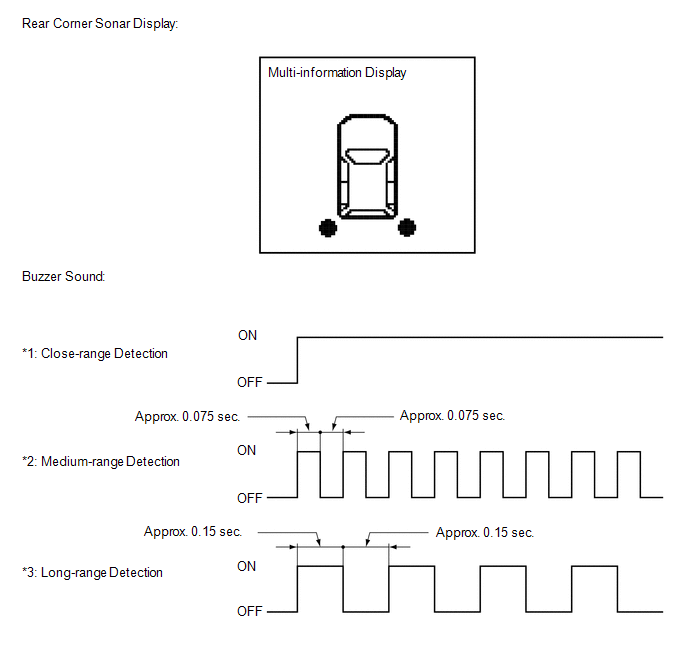
Standard:
Multi-information Display and Buzzer|
Detection Range |
During Judgment |
Obstacle |
|---|---|---|
|
*1 Close-range detection Within approx. 300 +/- 30 mm (11.8 +/- 1.2 in.) |
Buzzer: Sounds continuously |
60 mm (2.36 in.) diameter pole |
|
*2 Medium-range detection From approx. 300 +/- 30 to 450 +/- 50 mm (11.8 +/- 1.2 to 17.7 +/- 2.0 in.) |
Buzzer: Sounds intermittently (ON: 0.075 sec. / OFF: 0.075 sec.) |
60 mm (2.36 in.) diameter pole |
|
*3 Long-range detection From approx. 450+/- 50 to 600 +/- 60 mm (17.7 +/- 2.0 to 23.6 +/- 2.4 in.) |
Buzzer: Sounds intermittently (ON: 0.15 sec. / OFF: 0.15 sec.) |
60 mm (2.36 in.) diameter pole |
HINT:
Ultrasonic waves are used to measure the detection range; however, the detection range may vary depending on the ambient temperature.
(f) When the ultrasonic sensors (back sonar) have detected an obstacle, check the displays and check that the buzzer sounds.
Operation Condition|
Ignition Switch |
Clearance Sonar Main Switch |
Shift Lever Position |
Vehicle Speed |
|---|---|---|---|
|
ON |
On |
R |
- |
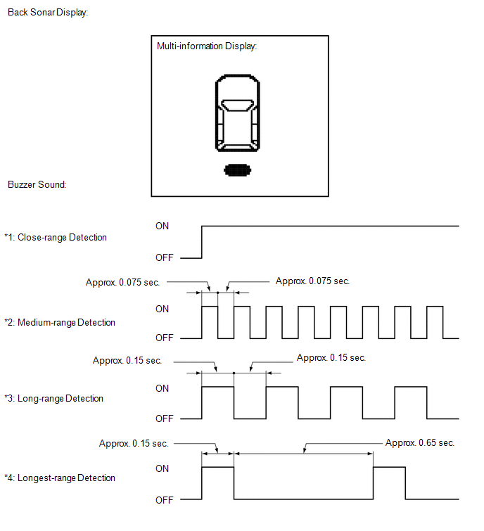
Standard:
Multi-information Display and Buzzer|
Detection Range |
During Detection |
Obstacle |
|---|---|---|
|
*1 Close-range detection Within approx. 350 +/- 40 mm (13.8 +/- 1.6 in.) |
Buzzer: Sounds continuously |
60 mm (2.36 in.) diameter pole |
|
*2 Medium-range detection From approx. 350 +/- 40 to 450 +/- 50 mm (13.8 +/- 1.6 to 17.7 +/- 2.0 in.) |
Buzzer: Sounds intermittently (ON: 0.075 sec. / OFF: 0.075 sec.) |
60 mm (2.36 in.) diameter pole |
|
*3 Long-range detection From approx. 450 +/- 50 to 600 +/- 60 mm (17.7 +/- 2.0 to 23.6 +/- 2.4 in.) |
Buzzer: Sounds intermittently (ON: 0.15 sec. / OFF: 0.15 sec.) |
60 mm (2.36 in.) diameter pole |
|
*4 Longest-range detection From approx. 600 +/- 60 to 1500 +/- 150 mm (23.6 +/- 2.4 to 59.1 +/- 5.9 in.) |
Buzzer: Sounds intermittently (ON: 0.15 sec. / OFF: 0.65 sec.) |
Wall |
HINT:
Ultrasonic waves are used to measure the detection range; however, the detection range may vary depending on the ambient temperature.
 How To Proceed With Troubleshooting
CAUTION / NOTICE / HINT
HINT:
Use the following procedures to troubleshoot the intuitive parking assist system.
PROCEDURE
1.
VEHICLE BROUGHT TO WORKSHOP
...
 Problem Symptoms Table
PROBLEM SYMPTOMS TABLE
HINT:
Use the table below to help determine the cause of problem symptoms. If multiple
suspected areas are listed, the potential causes of the symptoms are listed in order
...
Other materials about Toyota 4Runner:
Security Indicator Light Circuit
DESCRIPTION
When the engine immobiliser system is set, the security indicator flashes
continuously, but does not illuminate if the engine immobiliser system is
not set.
WIRING DIAGRAM
CAUTION / NOTICE / HINT
NOTICE:
Before replacing ...
Precaution
PRECAUTION
CAUTION:
This vehicle is equipped with a Supplemental Restraint System (SRS),
which consists of a steering pad, instrument panel passenger airbag, curtain
shield airbag, front seat side airbag, lower No. 1 instrument panel airbag, ...

0.008