Toyota 4Runner: Outer Mirror Switch
Components
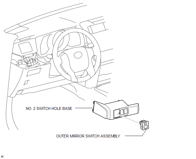
COMPONENTS
ILLUSTRATION
Removal
REMOVAL
PROCEDURE
1. REMOVE NO. 2 SWITCH HOLE BASE
.gif)
2. REMOVE OUTER MIRROR SWITCH ASSEMBLY
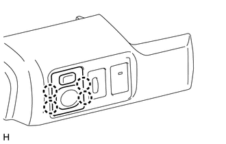
(a) Using a screwdriver, detach the 4 claws and remove the switch.
HINT:
Tape the screwdriver tip before use.
Inspection
INSPECTION
PROCEDURE
1. INSPECT OUTER MIRROR SWITCH ASSEMBLY
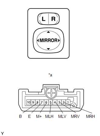
(a) Inspect the outer mirror switch assembly.
(1) Select "L" on the left/right adjustment switch.
(2) Measure the resistance according to the value(s) in the table below.
Standard Resistance:
|
Tester Connection |
Switch Condition |
Specified Condition |
|
|---|---|---|---|
|
4 (MLV) - 8 (B) 6 (M+) - 7 (E) |
UP |
Pressed |
Below 1 Ω |
|
Not pressed |
10 kΩ or higher |
||
|
4 (MLV) - 7 (E) 6 (M+) - 8 (B) |
DOWN |
Pressed |
Below 1 Ω |
|
Not pressed |
10 kΩ or higher |
||
|
5 (MLH) - 8 (B) 6 (M+) - 7 (E) |
LEFT |
Pressed |
Below 1 Ω |
|
Not pressed |
10 kΩ or higher |
||
|
5 (MLH) - 7 (E) 6 (M+) - 8 (B) |
RIGHT |
Pressed |
Below 1 Ω |
|
Not pressed |
10 kΩ or higher |
||
If the result is not as specified, replace the outer mirror switch assembly.
(3) Select "R" on the left/right adjustment switch.
(4) Measure the resistance according to the value(s) in the table below.
Standard Resistance:
|
Tester Connection |
Switch Condition |
Specified Condition |
|
|---|---|---|---|
|
3 (MRV) - 8 (B) 6 (M+) - 7 (E) |
UP |
Pressed |
Below 1 Ω |
|
Not pressed |
10 kΩ or higher |
||
|
3 (MRV) - 7 (E) 6 (M+) - 8 (B) |
DOWN |
Pressed |
Below 1 Ω |
|
Not pressed |
10 kΩ or higher |
||
|
2 (MRH) - 8 (B) 6 (M+) - 7 (E) |
LEFT |
Pressed |
Below 1 Ω |
|
Not pressed |
10 kΩ or higher |
||
|
2 (MRH) - 7 (E) 6 (M+) - 8 (B) |
RIGHT |
Pressed |
Below 1 Ω |
|
Not pressed |
10 kΩ or higher |
||
If the result is not as specified, replace the outer mirror switch assembly.
Text in Illustration|
*a |
Component without harness connected (Outer Mirror Switch Assembly) |
Installation
INSTALLATION
PROCEDURE
1. INSTALL OUTER MIRROR SWITCH ASSEMBLY
(a) Attach the 2 claws to install the switch.
2. INSTALL NO. 2 SWITCH HOLE BASE
.gif)
 Mirror (ext)
...

Other materials about Toyota 4Runner:
Panel Switches do not Function
CAUTION / NOTICE / HINT
NOTICE:
After replacing the navigation receiver assembly of vehicles subscribed to pay-type
satellite radio broadcasts, registration of the XM radio ID is necessary.
PROCEDURE
1.
CHECK PANEL SWITCH
...
Removal
REMOVAL
PROCEDURE
1. REMOVE REAR NO. 1 FLOOR STEP COVER (w/ Rear No. 2 Seat)
2. REMOVE QUARTER SCUFF PLATE RH (w/ Rear No. 2 Seat)
3. REMOVE REAR DOOR SCUFF PLATE RH
4. REMOVE REAR DOOR OPENING TRIM WEATHERSTRIP RH
5. REMOVE NO. 1 LUGGAGE COM ...

0.0249