Toyota 4Runner: Park / Neutral Position Switch Circuit
DESCRIPTION
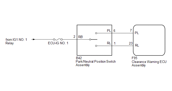
This circuit sends the park/neutral position switch assembly signals to the clearance warning ECU assembly.
WIRING DIAGRAM
CAUTION / NOTICE / HINT
NOTICE:
Inspect the fuses for circuits related to this system before performing the following inspection procedure.
PROCEDURE
|
1. |
INSPECT PARK/NEUTRAL POSITION SWITCH ASSEMBLY |
|
(a) Disconnect the B42 park/neutral position switch assembly connector. |
|
(b) Measure the resistance according to the value(s) in the table below.
Standard Resistance:
|
Tester Connection |
Condition |
Specified Condition |
|---|---|---|
|
1 (RL) - 2 (RB) |
Shift lever in R |
Below 1 Ω |
|
Shift lever not in R |
10 kΩ or higher |
|
|
2 (RB) - 6 (PL) |
Shift lever in P |
Below 1 Ω |
|
Shift lever not in P |
10 kΩ or higher |
|
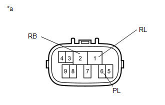
*a |
Component without harness connected (Park/Neutral Position Switch Assembly) |
|
Result |
Proceed to |
|---|---|
|
OK |
A |
|
NG (for A750F) |
B |
|
NG (for A750E) |
C |
| B | .gif) |
REPLACE PARK/NEUTRAL POSITION SWITCH ASSEMBLY |
| C | |
REPLACE PARK/NEUTRAL POSITION SWITCH ASSEMBLY |
|
.gif)
|
2. |
CHECK HARNESS AND CONNECTOR (PARK/NEUTRAL POSITION SWITCH ASSEMBLY - BATTERY) |
|
(a) Disconnect the B42 park/neutral position switch assembly connector. |
|
(b) Measure the voltage according to the value(s) in the table below.
Standard Voltage:
|
Tester Connection |
Switch Condition |
Specified Condition |
|---|---|---|
|
B42-2 (RB) - Body ground |
Ignition switch ON |
11 to 14 V |
|
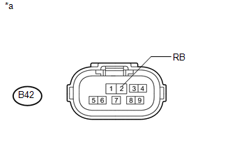
*a |
Front view of wire harness connector (to Park/Neutral Position Switch Assembly) |
| NG | |
REPAIR OR REPLACE HARNESS OR CONNECTOR |
|
|
3. |
CHECK HARNESS AND CONNECTOR (CLEARANCE WARNING ECU ASSEMBLY - PARK/NEUTRAL POSITION SWITCH ASSEMBLY) |
(a) Disconnect the F95 clearance warning ECU assembly connector.
(b) Disconnect the B42 park/neutral position switch assembly connector.
(c) Measure the resistance according to the value(s) in the table below.
Standard Resistance:
|
Tester Connection |
Condition |
Specified Condition |
|---|---|---|
|
F95-7 (PL) - B42-6 (PL) |
Always |
Below 1 Ω |
|
F95-23 (RL) - B42-1 (RL) |
Always |
Below 1 Ω |
|
F95-7 (PL) - Body ground |
Always |
10 kΩ or higher |
|
F95-23 (RL) - Body ground |
Always |
10 kΩ or higher |
| OK | |
PROCEED TO NEXT SUSPECTED AREA SHOWN IN PROBLEM SYMPTOMS TABLE |
| NG | |
REPAIR OR REPLACE HARNESS OR CONNECTOR |
 Terminals Of Ecu
TERMINALS OF ECU
1. CHECK CLEARANCE WARNING ECU
(a) Disconnect the F95 clearance warning ECU assembly connector.
(b) Measure the voltage and resistance according to the value(s) in the table
be ...
 Taillight Relay Circuit
DESCRIPTION
This is the power source circuit of the clearance warning ECU assembly.
WIRING DIAGRAM
CAUTION / NOTICE / HINT
NOTICE:
Inspect the fuses for circuits related to this system before p ...
Other materials about Toyota 4Runner:
Data List / Active Test
DATA LIST / ACTIVE TEST
1. ACTIVE TEST
HINT:
Using the Techstream to perform Active Tests allows relays, VSVs, actuators and
other items to be operated without removing any parts. This non-intrusive functional
inspection can be very useful because inter ...
Rear No. 1 Seat Assembly(for 60/40 Split Slide Walk-in Seat Type Lh Side)
Components
COMPONENTS
ILLUSTRATION
ILLUSTRATION
ILLUSTRATION
ILLUSTRATION
ILLUSTRATION
ILLUSTRATION
Removal
REMOVAL
CAUTION / NOTICE / HINT
CAUTION:
Wear protective gloves. Sharp areas on the parts may injure your hands.
PROCEDURE
...

0.0093