Toyota 4Runner: Back Door Support
Components
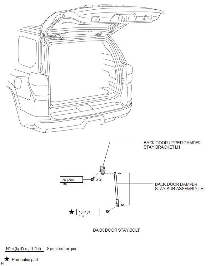
COMPONENTS
ILLUSTRATION
Removal
REMOVAL
PROCEDURE
1. REMOVE BACK DOOR DAMPER STAY SUB-ASSEMBLY LH
NOTICE:
- Avoid touching the piston rod as much as possible to prevent foreign matter from attaching to it. Be sure to hold the cylinder while servicing the vehicle.
- Do not wear cotton gloves or other similar materials when handling the piston rod. Fibers may attach to the rod and result in gas leaks.
- In order to prevent the piston rod from deforming, do not apply any horizontal load to the door damper stay.
|
(a) Using a screwdriver, remove the stop ring along the groove. HINT: Tape the screwdriver tip before use. Text in Illustration
|
|
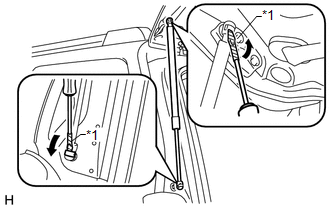
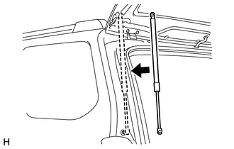
(b) Release the ball joint and remove the back door damper stay sub-assembly.
NOTICE:
Remove the back door damper stay sub-assembly while supporting the back door by hand.
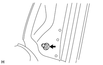
2. REMOVE BACK DOOR STAY BOLT
|
(a) Remove the back door stay bolt. NOTICE: If the hood support is detached from the ball joint, it becomes non-reusable. Therefore, do not detach the hood support from the ball joint unless replacing it. |
|
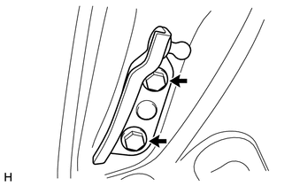
3. REMOVE BACK DOOR UPPER DAMPER STAY BRACKET LH
|
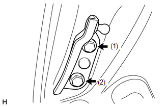
(a) Remove the 2 bolts and back door upper damper stay bracket. |
|
Disposal
DISPOSAL
PROCEDURE
1. DISPOSE OF BACK DOOR DAMPER STAY SUB-ASSEMBLY LH
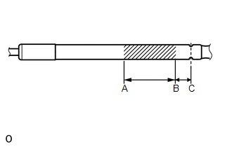
(a) Secure the back door damper stay sub-assembly horizontally in a vise with the piston rod pulled out.
|
(b) Wear safety glasses. Using a metal saw, slowly cut a groove between A and B shown in the illustration to release the gas. Standard:
CAUTION: Although the gas inside the back door damper stay sub-assembly is colorless, odorless and harmless, metal debris may scatter. Therefore, cover the back door damper stay sub-assembly with a piece of cloth or other material. |
|
Installation
INSTALLATION
PROCEDURE
1. INSTALL BACK DOOR UPPER DAMPER STAY BRACKET LH
|
(a) Install the back door upper damper stay bracket with the 2 bolts. HINT: Tighten the bolts in the order shown in the illustration. Torque: 20 N·m {204 kgf·cm, 15 ft·lbf} |
|
2. INSTALL BACK DOOR STAY BOLT
(a) Clean the threaded portion on the vehicle body with a non-residue solvent.
(b) Apply adhesive to the threads of the bolt.
Adhesive:
Toyota Genuine Adhesive 1324, Three Bond 1324 or equivalent
|
(c) Install the back door stay bolt. Torque: 18 N·m {184 kgf·cm, 13 ft·lbf} |
|
.png)
3. INSTALL BACK DOOR DAMPER STAY SUB-ASSEMBLY LH
NOTICE:
- Avoid touching the piston rod as much as possible to prevent foreign matter from attaching to it. Be sure to hold the cylinder while servicing the vehicle.
- Do not wear cotton gloves or other similar materials when handling the piston rod. Fibers may attach to the rod and result in gas leaks.
- In order to prevent the piston rod from deforming, do not apply any horizontal load to the door damper stay.
|
(a) Install a new back door damper stay sub-assembly. NOTICE:
|
|
 Back Door Opener Switch
Components
COMPONENTS
ILLUSTRATION
Disassembly
DISASSEMBLY
PROCEDURE
1. REMOVE ASSIST STRAP HOLE COVER
2. REMOVE ASSIST STRAP ASSEMBLY
3. REMOVE BACK DOOR TRIM PANEL ASSEMBLY
4 ...
 Front Door
...
Other materials about Toyota 4Runner:
Radiator Grille
Components
COMPONENTS
ILLUSTRATION
Removal
REMOVAL
PROCEDURE
1. REMOVE UPPER RADIATOR SUPPORT SEAL
2. REMOVE FRONT BUMPER COVER
3. REMOVE FRONT BUMPER COVER (w/ Intuitive Parking Assist System)
4. REMOVE RADIATOR GRILLE
(a) ...
Installation
INSTALLATION
CAUTION / NOTICE / HINT
HINT:
Use the same procedure for both the RH and LH sides.
The procedure listed below is for the LH side.
PROCEDURE
1. INSTALL FRONT BUMPER BAR REINFORCEMENT LH (w/o Intuitive Parking Assist System)
...

0.0067