Toyota 4Runner: Parking Brake Switch Circuit
DESCRIPTION
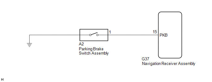
This circuit is from the parking brake switch assembly to the navigation receiver assembly.
WIRING DIAGRAM
PROCEDURE
|
1. |
CHECK VEHICLE SIGNAL (OPERATION CHECK) |
|
(a) Display the "Vehicle Signal Check Mode" screen (See page
|
|
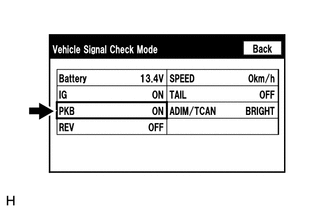
(b) Check that the display changes between ON and OFF according to the parking brake operation.
OK:
|
Parking Brake Condition |
Display |
|---|---|
|
Applied |
ON |
|
Released |
OFF |
HINT:
This display is updated once per second. As a result, it is normal for the display to lag behind the actual parking brake operation.
| OK | .gif) |
PROCEED TO NEXT SUSPECTED AREA SHOWN IN PROBLEM SYMPTOMS TABLE |
|
.gif)
|
2. |
CHECK HARNESS AND CONNECTOR (PARKING BRAKE SWITCH ASSEMBLY - NAVIGATION RECEIVER ASSEMBLY) |
(a) Disconnect the G37 navigation receiver assembly connector.
(b) Disconnect the A2 parking brake switch assembly connector.
(c) Measure the resistance according to the value(s) in the table below.
Standard Resistance:
|
Tester Connection |
Condition |
Specified Condition |
|---|---|---|
|
G37-15 (PKB) - A2-1 |
Always |
Below 1 Ω |
|
G37-15 (PKB) - Body ground |
Always |
10 kΩ or higher |
| NG | |
REPAIR OR REPLACE HARNESS OR CONNECTOR |
|
|
3. |
INSPECT PARKING BRAKE SWITCH ASSEMBLY |
(a) Remove the parking brake switch assembly (See page
.gif) ).
).
(b) Inspect the parking brake switch assembly (See page
).
| OK | |
PROCEED TO NEXT SUSPECTED AREA SHOWN IN PROBLEM SYMPTOMS TABLE |
| NG | |
REPLACE PARKING BRAKE SWITCH ASSEMBLY |
 Illumination Circuit
DESCRIPTION
Power is supplied to the navigation receiver assembly and steering pad switch
assembly illumination when the light control switch is in the tail or head position.
WIRING DIAGRAM
CAU ...
 Speaker Circuit
DESCRIPTION
If there is a short in a speaker circuit, the stereo component amplifier
assembly detects it and stops output to the speakers.
Thus sound cannot be heard from the speakers ...
Other materials about Toyota 4Runner:
Operation Check
OPERATION CHECK
1. CHECK INITIAL CHECK FUNCTION
(a) Check the initial check function for the buzzer.
(1) When the back sonar or clearance sonar switch assembly is turned on, check
that the following occurs: 1) after 0.2 seconds, the buzzer sounds for ap ...
Diagnosis System
DIAGNOSIS SYSTEM
1. DESCRIPTION
(a) When troubleshooting On-Board Diagnostic (OBD II) vehicles, the vehicle must
be connected to the OBD II scan tool (complying with SAE J1987). Various data output
from the vehicle's ECM can then be read.
(b) OBD II ...

0.0119