Toyota 4Runner: Illumination Circuit
DESCRIPTION
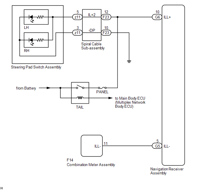
Power is supplied to the navigation receiver assembly and steering pad switch assembly illumination when the light control switch is in the tail or head position.
WIRING DIAGRAM
CAUTION / NOTICE / HINT
NOTICE:
- The vehicle is equipped with a Supplemental Restraint System (SRS) which
includes components such as airbags. Before servicing (including removal
or installation of parts), be sure to read the precaution for Supplemental
Restraint System (See page
.gif) ).
). - Inspect the fuse for circuits related to this system before performing the following inspection procedure.
PROCEDURE
|
1. |
CHECK ILLUMINATION |
(a) Check if the illumination for the navigation receiver assembly, steering pad switch assembly, heater control switch or others (hazard switch, transmission control switch, etc.) comes on when the light control switch is turned to the head or tail position.
|
Result |
Proceed to |
|---|---|
|
Illumination comes on for all components except steering pad switch assembly. |
A |
|
Illumination comes on for all components except navigation receiver assembly. |
B |
|
Illumination comes on only for steering pad switch assembly. |
C |
|
No illumination comes on (navigation receiver assembly, hazard switch, heater control switch, etc.). |
D |
| B | .gif) |
GO TO STEP 5 |
| C | |
GO TO METER / GAUGE SYSTEM |
| D | |
GO TO LIGHTING SYSTEM |
|
.gif)
|
2. |
CHECK HARNESS AND CONNECTOR (ILLUMINATION SIGNAL) |
(a) Disconnect the F23 spiral cable sub-assembly connector.
(b) Measure the voltage according to the value(s) in the table below.
Standard Voltage:
|
Tester Connection |
Switch Condition |
Specified Condition |
|---|---|---|
|
F23-12 (IL+2) - Body ground |
Light control switch in the tail or head position |
11 to 14 V |
| NG | |
REPAIR OR REPLACE HARNESS OR CONNECTOR |
|
|
3. |
INSPECT STEERING PAD SWITCH ASSEMBLY |
(a) Remove the steering pad switch assembly (See page
).
(b) Inspect the steering pad switch assembly (See page
).
| NG | |
REPLACE STEERING PAD SWITCH ASSEMBLY |
|
|
4. |
INSPECT SPIRAL CABLE SUB-ASSEMBLY |
(a) Inspect the spiral cable sub-assembly (See page
).
NOTICE:
- The spiral cable sub-assembly is an important part of the SRS airbag system. Incorrect removal or installation of the spiral cable sub-assembly may prevent the airbag from deploying. Refer to the pages shown in the brackets.
- As the spiral cable sub-assembly may break, do not rotate the spiral cable sub-assembly more than the specified amount.
HINT:
- Removal (See page )
- Installation (See page )
| OK | |
REPAIR OR REPLACE HARNESS OR CONNECTOR (SPIRAL CABLE SUB-ASSEMBLY - BODY GROUND) |
| NG | |
REPLACE SPIRAL CABLE SUB-ASSEMBLY |
|
5. |
CHECK HARNESS AND CONNECTOR (ILLUMINATION SIGNAL) |
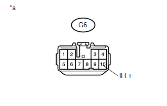
(a) Disconnect the G6 navigation receiver assembly connector.
|
(b) Measure the voltage according to the value(s) in the table below. Standard Voltage:
|
|
| NG | |
REPAIR OR REPLACE HARNESS OR CONNECTOR |
|
|
6. |
CHECK HARNESS AND CONNECTOR (NAVIGATION RECEIVER ASSEMBLY - COMBINATION METER ASSEMBLY) |
(a) Disconnect the G5 navigation receiver assembly connector.
(b) Disconnect the F14 combination meter assembly connector.
(c) Measure the resistance according to the value(s) in the table below.
Standard Resistance:
|
Tester Connection |
Condition |
Specified Condition |
|---|---|---|
|
G5-5 (ILL-) - F14-11 (ILL-) |
Always |
Below 1 Ω |
|
G5-5 (ILL-) - Body ground |
Always |
10 kΩ or higher |
| OK | |
PROCEED TO NEXT SUSPECTED AREA SHOWN IN PROBLEM SYMPTOMS TABLE |
| NG | |
REPAIR OR REPLACE HARNESS OR CONNECTOR |
 Steering Pad Switch Circuit
DESCRIPTION
This circuit sends an operation signal from the steering pad switch assembly
to the navigation receiver assembly.
If there is an open in the circuit, the audio system cannot be operate ...
 Parking Brake Switch Circuit
DESCRIPTION
This circuit is from the parking brake switch assembly to the navigation receiver
assembly.
WIRING DIAGRAM
PROCEDURE
1.
CHECK VEHICLE SIGNAL (OPERATION CHECK ...
Other materials about Toyota 4Runner:
Removal
REMOVAL
PROCEDURE
1. REMOVE SPIRAL CABLE SUB-ASSEMBLY
(a) Remove the spiral cable sub-assembly (See page
).
2. REMOVE WINDSHIELD WIPER SWITCH ASSEMBLY
3. REMOVE HEADLIGHT DIMMER SWITCH ASSEMBLY
(a) Disconnect the connector.
...
Removal
REMOVAL
PROCEDURE
1. REMOVE INSTRUMENT PANEL SUB-ASSEMBLY
(a) Remove the instrument panel sub-assembly (See page
).
2. REMOVE NO. 1 HEATER TO REGISTER DUCT
3. REMOVE NO. 2 HEATER TO REGISTER DUCT
4. REMOVE NO. 1 SIDE DEFROSTER NOZZLE DUCT
5. ...

0.0089