Toyota 4Runner: Parts Location
Toyota 4Runner Service Manual / Vehicle Interior / Door Lock / Power Door Lock Control System / Parts Location
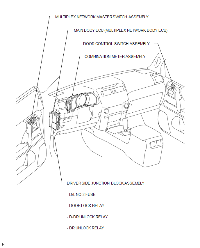
PARTS LOCATION
ILLUSTRATION
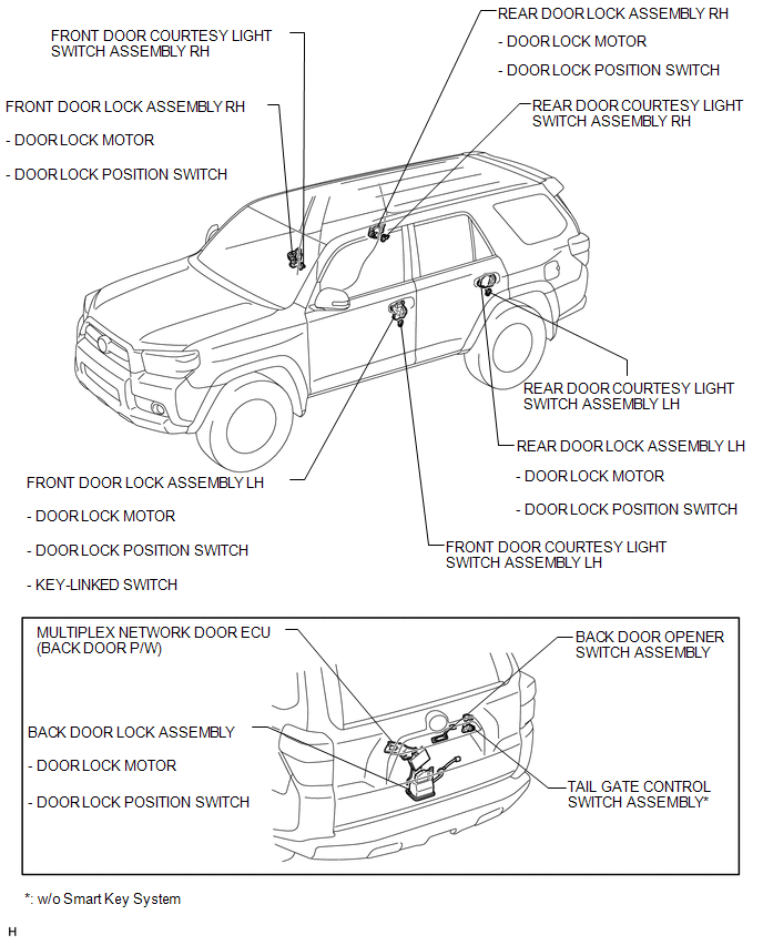
ILLUSTRATION
 Precaution
PRECAUTION
1. IGNITION SWITCH EXPRESSION
HINT:
The type of ignition switch used on this model differs according to the specifications
of the vehicle. The expressions listed in the table below are ...
 System Diagram
SYSTEM DIAGRAM
Communication Table
Sender
Receiver
Signal
Line
Combination meter assembly
Main body ECU (Multiplex network ...
Other materials about Toyota 4Runner:
Precaution
PRECAUTION
1. IGNITION SWITCH EXPRESSION
HINT:
The type of ignition switch used on this model differs according to the specifications
of the vehicle. The expressions listed in the table below are used in this section.
Expression
Ign ...
Transmitter ID not Received in Main Mode (C2126/26)
DESCRIPTION
After all IDs are registered, DTC C2126/26 is stored in the tire pressure warning
ECU and the tire pressure warning light blinks for 1 minute and then comes on.
When the tire pressure warning ECU successfully receives information from all
the ...
© 2016-2026 | www.to4runner.net

0.1371
0.1371