Toyota 4Runner: System Diagram
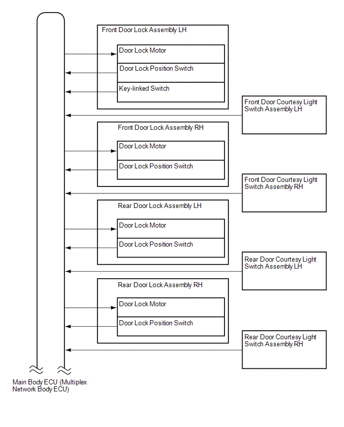
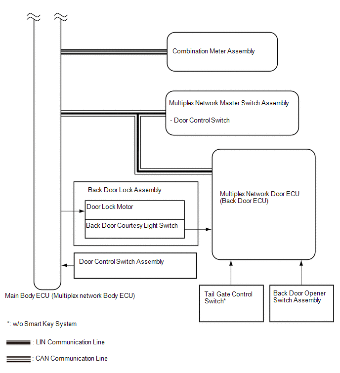
SYSTEM DIAGRAM
 Communication Table
|
Sender |
Receiver |
Signal |
Line |
|---|---|---|---|
|
Combination meter assembly |
Main body ECU (Multiplex network body ECU) |
Vehicle speed signal |
CAN |
|
Multiplex network master switch assembly |
Main body ECU (Multiplex network body ECU) |
Driver side door manual lock switch signal |
LIN |
|
Multiplex network door ECU (Back door P/W) |
Main body ECU (Multiplex network body ECU) |
|
LIN |
- *: w/o Smart Key System
 Parts Location
PARTS LOCATION
ILLUSTRATION
ILLUSTRATION
...
 How To Proceed With Troubleshooting
CAUTION / NOTICE / HINT
HINT:
Use these procedures to troubleshoot the power door lock control system.
*: Use the Techstream.
PROCEDURE
1.
VEHICLE BROUG ...
Other materials about Toyota 4Runner:
Messages displayed on the accessory meter
Depending on switch operation, one of the following messages may appear on
the accessory meter to provide guidance on transfer mode selection etc:
Multi-terrain Select is temporarily canceled when
The front-wheel drive control lever or switch is shift ...
Removal
REMOVAL
CAUTION / NOTICE / HINT
NOTICE:
Be sure to read PRECAUTION before performing this procedure (See page
).
PROCEDURE
1. REMOVE FRONT WHEEL
2. REMOVE REAR WHEEL
3. REMOVE CENTER CONTROL ABSORBER ASSEMBLY LH
(a) While using a wrench to ...

0.0277