Toyota 4Runner: Power Supply Voltage Malfunction (C1882/82)
DESCRIPTION
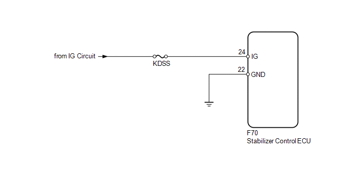
The stabilizer control ECU recognizes the ignition switch ON signal based on the voltage input to the IG terminal.
|
DTC Code |
DTC Detection Condition |
Trouble Area |
|---|---|---|
|
C1882/82 |
The IG terminal voltage is 10 V or less or 16 V or higher for 0.5 seconds. |
|
WIRING DIAGRAM
CAUTION / NOTICE / HINT
NOTICE:
Inspect the fuses for circuits related to this system before performing the following inspection procedure.
PROCEDURE
|
1. |
READ VALUE USING TECHSTREAM (IG POWER SOURCE VOLTAGE) |
(a) Turn the ignition switch off.
(b) Connect the Techstream to the DLC3.
(c) Turn the ignition switch to ON.
(d) Turn the Techstream on.
(e) Enter the following menus: Chassis / KDSS / Data List.
(f) Select the item below in the Data List, and read the value displayed on the Techstream.
KDSS|
Tester Display |
Measurement Item/Range |
Normal Condition |
Diagnostic Note |
|---|---|---|---|
|
IG Power Source Voltage |
IG Power Source Voltage/ Min.: 0.0 V Max.: 25.5 V |
Ignition switch ON: 11 to 14 V |
- |
Standard voltage:
11 to 14 V
| NG | .gif) |
GO TO STEP 3 |
|
.gif)
|
2. |
RECONFIRM DTC |
(a) Clear the DTCs (See page .gif) ).
).
(b) Check for DTCs (See page ).
Result
|
Result |
Proceed to |
|---|---|
|
DTC is output |
A |
|
DTC is not output |
B |
| A | |
REPLACE STABILIZER CONTROL ECU |
| B | |
USE SIMULATION METHOD TO CHECK |
|
3. |
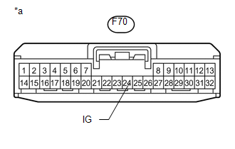
CHECK HARNESS AND CONNECTOR (IG TERMINAL) |
(a) Disconnect the stabilizer control ECU connector.
|
(b) Measure the voltage according to the value(s) in the table below. Standard Voltage:
|
|
| NG | |
REPAIR OR REPLACE HARNESS OR CONNECTOR |
|
|
4. |
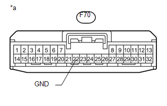
CHECK HARNESS AND CONNECTOR (GND TERMINAL) |
(a) Disconnect the stabilizer control ECU connector.
|
(b) Measure the resistance according to the value(s) in the table below. Standard Resistance:
|
|
| OK | |
REPLACE STABILIZER CONTROL ECU |
| NG | |
REPAIR OR REPLACE HARNESS OR CONNECTOR |
 On-vehicle Inspection
ON-VEHICLE INSPECTION
PROCEDURE
1. INSPECT INDICATOR LIGHT
(a) Check that the KDSS indicator light comes on for 2 seconds when the ignition
switch is turned to ON.
If the indicator check result ...
 Speed Sensor Circuit Malfunction (C1883/83)
DESCRIPTION
The stabilizer control ECU receives the speed signal from the skid control ECU
via CAN communication.
DTC Code
DTC Detection Condition
Trouble Area
...
Other materials about Toyota 4Runner:
Parking brake
To set the parking brake, fully depress the parking brake pedal with your
left foot while depressing the brake pedal with your right foot.
(Depressing the pedal again releases the parking brake.)
Usage in winter time
See “Winter driving tips” for pa ...
Radio Broadcast cannot be Received or Poor Reception
CAUTION / NOTICE / HINT
NOTICE:
After replacing the navigation receiver assembly of vehicles subscribed to pay-type
satellite radio broadcasts, XM radio ID registration is necessary.
PROCEDURE
1.
CHECK NAVIGATION RECEIVER ASSEMBLY
...

0.0086