Toyota 4Runner: Pressure Control Solenoid "A" Electrical (Shift Solenoid Valve SL1) (P0748)
DESCRIPTION
Shifting from 1st to 5th is performed in combination with the ON and OFF operation
of the shift solenoid valves SL1, SL2, S1, S2 and SR, which are controlled by the
ECM. If an open or short circuit occurs in one of the shift solenoid valves, the
ECM controls the remaining normal shift solenoid valves to allow the vehicle to
be operated smoothly (See page .gif) ).
).
|
DTC Code |
DTC Detection Condition |
Trouble Area |
|---|---|---|
|
P0748 |
The ECM checks for an open or short in the shift solenoid valve SL1 circuit while driving and shifting between 4th and 5th gear (1-trip detection logic). Output signal duty equals 100%. HINT: SL1 output signal duty is less than 100% under normal conditions. |
|
MONITOR DESCRIPTION
This DTC indicates an open or short in the shift solenoid valve SL1 circuit. The ECM commands gear shifts by turning the shift solenoid valves ON/OFF. When there is an open or short circuit in any shift solenoid valve circuit, the ECM detects the problem, illuminates the MIL and stores the DTC. Then the ECM performs the fail-safe function and turns the other normal shift solenoid valves ON/OFF. In case of an open or short circuit, the ECM stops sending current to the circuit.
While driving and shifting between 4th and 5th gears, if the ECM detects an open
or short in the shift solenoid valve SL1 circuit, the ECM determines there is a
malfunction (See page ).
MONITOR STRATEGY
|
Related DTCs |
P0748: Shift solenoid valve SL1/Range check |
|
Required sensors/Components |
Shift solenoid valve SL1 |
|
Frequency of operation |
Continuous |
|
Duration |
1 sec. |
|
MIL operation |
Immediate |
|
Sequence of operation |
None |
TYPICAL ENABLING CONDITIONS
All|
The monitor will run whenever the following DTCs are not stored |
None |
|
Battery voltage |
8 V or higher |
|
Ignition switch |
ON |
|
Starter |
OFF |
|
Solenoid current cut status |
Not cut |
|
Battery voltage |
11 V or higher |
|
Target duty cycle |
19% or more |
|
Target duty cycle |
100% |
TYPICAL MALFUNCTION THRESHOLDS
|
Solenoid status from solenoid driver MIC |
Failure |
COMPONENT OPERATING RANGE
|
Output signal duty |
Less than 100% |
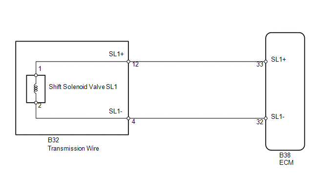
WIRING DIAGRAM
CAUTION / NOTICE / HINT
NOTICE:
Perform the universal trip to clear permanent DTCs (See page
).
HINT:
The shift solenoid valve SL1 is turned ON/OFF normally when the shift lever is in D.
|
ECM gear shift command |
1st |
2nd |
3rd |
4th |
5th |
|
Shift solenoid valve SL1 |
OFF |
OFF |
OFF |
OFF |
ON |
PROCEDURE
|
1. |
INSPECT TRANSMISSION WIRE (SHIFT SOLENOID VALVE SL1) |
|
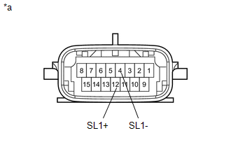
(a) Disconnect the B32 transmission wire connector. |
|
(b) Measure the resistance according to the value(s) in the table below.
Standard Resistance:
|
Tester Connection |
Condition |
Specified Condition |
|---|---|---|
|
12 (SL1+) - 4 (SL1-) |
20°C (68°F) |
5.0 to 5.6 Ω |
|
12 (SL1+) - Body ground |
Always |
10 kΩ or higher |
|
4 (SL1-) - Body ground |
Always |
10 kΩ or higher |
|
*a |
Component without harness connected (Transmission Wire) |
| NG | .gif) |
GO TO STEP 3 |
|
.gif)
|
2. |
CHECK HARNESS AND CONNECTOR (TRANSMISSION WIRE - ECM) |
|
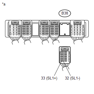
(a) Disconnect the B38 ECM connector. |
|
(b) Measure the resistance according to the value(s) in the table below.
Standard Resistance:
|
Tester Connection |
Condition |
Specified Condition |
|---|---|---|
|
B38-33 (SL1+) - B38-32 (SL1-) |
20°C (68°F) |
5.0 to 5.6 Ω |
|
B38-33 (SL1+) - Body ground |
Always |
10 kΩ or higher |
|
B38-32 (SL1-) - Body ground |
Always |
10 kΩ or higher |
|
*a |
Rear view of wire harness connector (to ECM) |
| OK | |
REPLACE ECM |
| NG | |
REPAIR OR REPLACE HARNESS OR CONNECTOR |
|
3. |
INSPECT SHIFT SOLENOID VALVE SL1 |
| OK | |
REPAIR OR REPLACE TRANSMISSION WIRE |
| NG | |
REPLACE SHIFT SOLENOID VALVE SL1 |
 Pressure Control Solenoid "B" Performance (Shift Solenoid Valve SL2) (P0776)
DESCRIPTION
The ECM uses signals from the output shaft speed sensor and input speed sensor
to detect the actual gear position (1st, 2nd, 3rd, 4th or 5th gear).
Then the ECM compares the actual gea ...
 Output Speed Sensor Circuit No Signal (P0722)
DESCRIPTION
The speed sensor SP2 detects the rotation speed of the transmission output shaft
and sends signals to the ECM. The ECM determines the vehicle speed based on these
signals. An AC volta ...
Other materials about Toyota 4Runner:
Terminals Of Ecu
TERMINALS OF ECU
1. CHECK POWER STEERING ECU ASSEMBLY
(a) Measure the voltage and resistance according to the value(s) in the table
below.
Terminal No. (Symbol)
Wiring Color
Terminal Description
Condition
...
Problem Symptoms Table
PROBLEM SYMPTOMS TABLE
HINT:
Use the table below to help determine the cause of problem symptoms.
If multiple suspected areas are listed, the potential causes of the symptoms
are listed in order of probability in the "Suspected Area" ...

0.0276