Toyota 4Runner: Rear No. 1 Seat Inner Belt Assembly(for 60/40 Split Double-folding Seat Type Rh Side)
Components
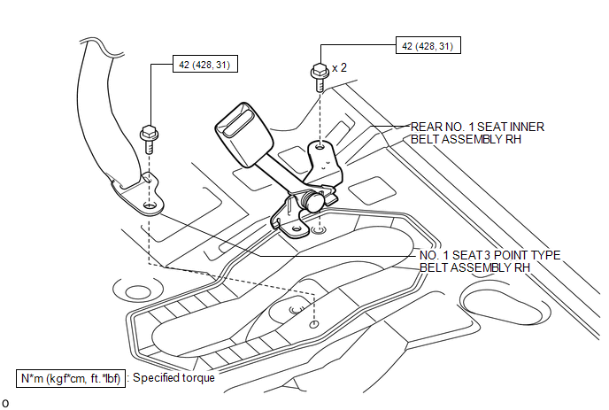
COMPONENTS
ILLUSTRATION
Removal
REMOVAL
PROCEDURE
1. DISCONNECT REAR NO. 1 SEAT OUTER BELT ASSEMBLY RH
|
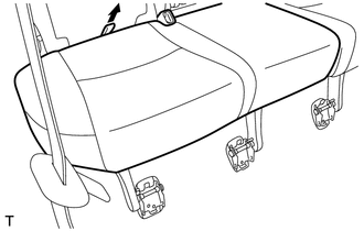
(a) Pull the rear seat cushion band, release the lock and lift up the back of the seat cushion to rotate it forward. |
|
|
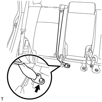
(b) Remove the bolt and disconnect the outer belt floor anchor. |
|
2. REMOVE REAR NO. 1 SEAT INNER BELT ASSEMBLY RH
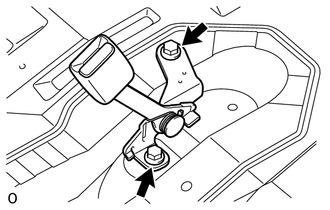
(a) Remove the 2 bolts and inner belt.
Installation
INSTALLATION
PROCEDURE
1. INSTALL REAR NO. 1 SEAT INNER BELT ASSEMBLY RH
(a) Install the inner belt with the 2 bolts.
Torque:
42 N·m {428 kgf·cm, 31 ft·lbf}
2. CONNECT REAR NO. 1 SEAT OUTER BELT ASSEMBLY RH

(a) Connect the outer belt floor anchor with the bolt.
Torque:
42 N·m {428 kgf·cm, 31 ft·lbf}
NOTICE:
The anchor part of the seat belt must not overlap the protruding part.
Text in Illustration|
*a |
Protruding Part |
(b) Return the seat cushion to its original position.
 Rear No. 1 Seat Inner Belt Assembly(for 60/40 Split Double-folding Seat Type
Lh Side)
Rear No. 1 Seat Inner Belt Assembly(for 60/40 Split Double-folding Seat Type
Lh Side)
Components
COMPONENTS
ILLUSTRATION
Installation
INSTALLATION
PROCEDURE
1. INSTALL REAR NO. 1 SEAT INNER BELT ASSEMBLY LH
(a) Install the inner belt with the bolt.
Torque:
42 N·m {428 ...

Other materials about Toyota 4Runner:
How To Proceed With Troubleshooting
CAUTION / NOTICE / HINT
HINT:
Use these procedures to troubleshoot the power window control system.
*: Use the Techstream.
PROCEDURE
1.
VEHICLE BROUGHT TO WORKSHOP
NEXT
...
How To Proceed With Troubleshooting
CAUTION / NOTICE / HINT
HINT:
Use these procedures to troubleshoot the rear view monitor system.
PROCEDURE
1.
VEHICLE BROUGHT TO WORKSHOP
NEXT
2.
...
0.0176