Toyota 4Runner: Rear Shock Absorber(w/ Reas)
Components
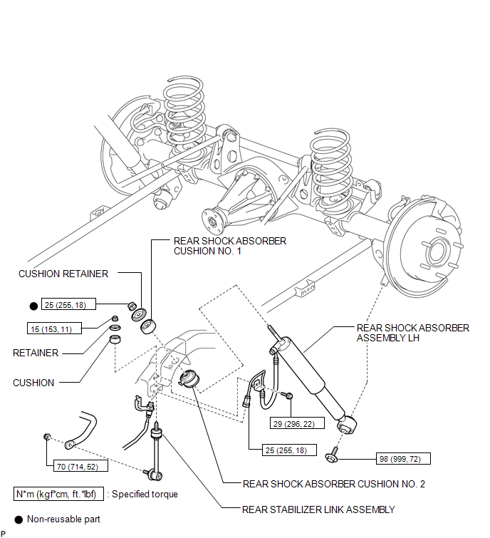
COMPONENTS
ILLUSTRATION
Removal
REMOVAL
CAUTION / NOTICE / HINT
NOTICE:
Be sure to read the precaution before performing this procedure (See page
.gif) ).
).
HINT:
- Use the same procedure for the RH and LH sides.
- The procedure listed below is for the LH side.
PROCEDURE
1. REMOVE REAR WHEEL
2. REMOVE REAR STABILIZER LINK ASSEMBLY
3. REMOVE REAR SHOCK ABSORBER ASSEMBLY LH
|
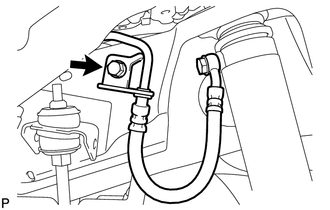
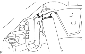
(a) Remove the bolt and disconnect the bracket. |
|
|
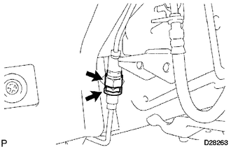
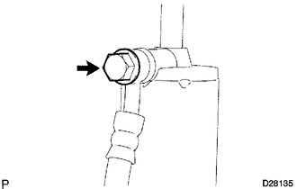
(b) Using a wrench to hold the bracket, remove the joint. NOTICE: Check that all shock absorbers are fully extended to the normal suspension rebound point. |
|
|
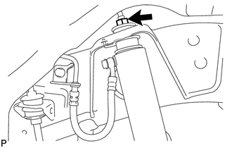
(c) Remove the bolt and disconnect the rear shock absorber assembly LH from the rear axle housing. NOTICE: Make sure that the rear axle housing is supported so that the rear shock absorber assembly LH is not extended beyond the normal suspension rebound point. |
|
.png)
(d) Remove the nut, cushion retainer, cushion No. 1 and rear shock absorber assembly LH.
NOTICE:
- Remove the rear shock absorber assembly LH with the shock absorber rod fully extended.
- Be sure to hold the body part of the rear shock absorber assembly LH when carrying it.
(e) Remove the cushion No. 2 from the rear shock absorber assembly LH.
Installation
INSTALLATION
CAUTION / NOTICE / HINT
NOTICE:
Be sure to read the precaution before performing this procedure (See page
.gif) ).
).
HINT:
- Use the same procedure for the RH and LH sides.
- The procedure listed below is for the LH side.
- A bolt without a torque specification is shown in the standard bolt
chart (See page ).
PROCEDURE
1. INSTALL REAR SHOCK ABSORBER ASSEMBLY LH
(a) Install the cushion No. 2 to the rear shock absorber assembly LH.
(b) Install the cushion retainer, cushion No. 1 and rear shock absorber assembly LH with the nut.
Torque:
25 N·m {255 kgf·cm, 18 ft·lbf}
NOTICE:
Be sure to fit the positioning protrusion of the bracket into a hole on the frame.
(c) Install the rear shock absorber assembly LH with the bolt.
(d) Install the bracket with the bolt.
Torque:
29 N·m {296 kgf·cm, 21 ft·lbf}
(e) Using a wrench to hold the bracket, install the joint.
HINT:
Tighten the joint so that the gap is 1 mm (0.0394 in.).
Torque:
25 N·m {255 kgf·cm, 18 ft·lbf}
2. INSTALL REAR STABILIZER LINK ASSEMBLY
3. INSTALL REAR WHEEL
Torque:
for aluminum wheel :
103 N·m {1050 kgf·cm, 76 ft·lbf}
for steel wheel :
112 N·m {1142 kgf·cm, 83 ft·lbf}
4. STABILIZE SUSPENSION
(a) Lower the vehicle.
(b) Bounce the vehicle up and down several times to stabilize the suspension.
5. TIGHTEN REAR SHOCK ABSORBER ASSEMBLY LH
(a) Tighten the bolt.
Torque:
98 N·m {999 kgf·cm, 72 ft·lbf}
6. INSPECT FOR FLUID LEAK
(a) Inspect for fluid leaks (See page ).
Disposal
DISPOSAL
PROCEDURE
1. DISPOSE OF REAR SHOCK ABSORBER ASSEMBLY LH
|
(a) Loosen the bolt. |
|
(b) Drain the absorber oil.
 Rear Lower Arm
Components
COMPONENTS
ILLUSTRATION
Removal
REMOVAL
CAUTION / NOTICE / HINT
HINT:
Use the same procedure for the RH and LH sides.
The procedure listed below is for the LH side. ...
 Rear Shock Absorber(w/o Reas)
Components
COMPONENTS
ILLUSTRATION
Removal
REMOVAL
CAUTION / NOTICE / HINT
HINT:
Use the same procedure for the RH and LH sides.
The procedure listed below is for the LH side. ...
Other materials about Toyota 4Runner:
Installation
INSTALLATION
CAUTION / NOTICE / HINT
CAUTION:
Wear protective gloves. Sharp areas on the parts may injure your hands.
HINT:
Use the same procedure for the RH and LH sides.
The procedure listed below is for the LH side.
PROCEDURE
1. INS ...
Removal
REMOVAL
CAUTION / NOTICE / HINT
HINT:
Use the same procedure for the RH and LH sides.
The procedure listed below is for the LH side.
PROCEDURE
1. REMOVE REAR NO. 2 SEAT ASSEMBLY
(a) Remove the rear No. 2 seat assembly (See page
).
2. ...

0.0066