Toyota 4Runner: Rear Lower Arm
Components
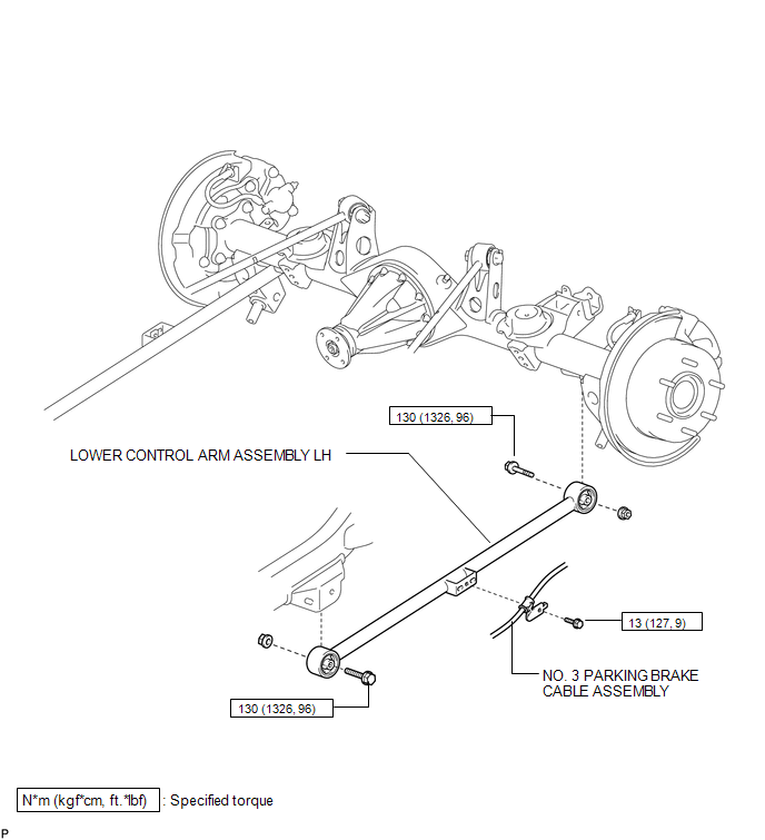
COMPONENTS
ILLUSTRATION
Removal
REMOVAL
CAUTION / NOTICE / HINT
HINT:
- Use the same procedure for the RH and LH sides.
- The procedure listed below is for the LH side.
PROCEDURE
1. REMOVE REAR WHEEL
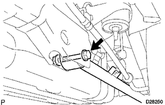
2. DISCONNECT NO. 3 PARKING BRAKE CABLE ASSEMBLY
(a) Remove the bolt and disconnect the No. 3 parking brake cable assembly.
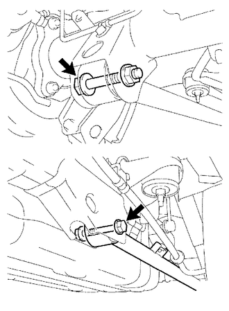
3. REMOVE LOWER CONTROL ARM ASSEMBLY LH
|
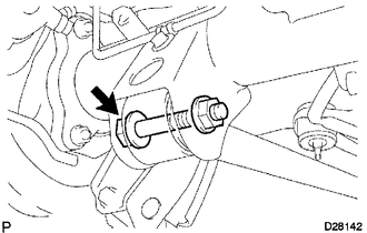
(a) Remove the nut and bolt from the rear axle housing. HINT: Turn the bolt while holding the nut. |
|
|
(b) Remove the nut, bolt and lower control arm assembly. HINT: Turn the bolt while holding the nut. |
|
Installation
INSTALLATION
CAUTION / NOTICE / HINT
HINT:
- Use the same procedure for the RH and LH sides.
- The procedure listed below is for the LH side.
- A bolt without a torque specification is shown in the standard bolt
chart (See page
.gif) ).
).
PROCEDURE
1. TEMPORARILY INSTALL LOWER CONTROL ARM ASSEMBLY LH
|
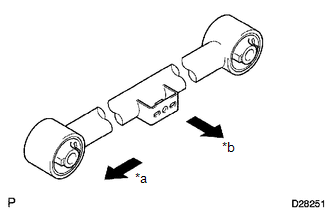
(a) Temporarily install the lower control arm assembly with the bolt and nut. Text in Illustration
HINT: Install the lower control arm assembly as shown in the illustration. |
|
(b) Temporarily install the lower control arm assembly to the rear axle housing with the nut and bolt.
2. CONNECT NO. 3 PARKING BRAKE CABLE ASSEMBLY
(a) Connect the No. 3 parking brake cable assembly with the bolt.
Torque:
13 N·m {127 kgf·cm, 9 ft·lbf}
3. INSTALL REAR WHEEL
Torque:
for aluminum wheel :
103 N·m {1050 kgf·cm, 76 ft·lbf}
for steel wheel :
112 N·m {1142 kgf·cm, 83 ft·lbf}
4. STABILIZE SUSPENSION
5. TIGHTEN LOWER CONTROL ARM ASSEMBLY LH
|
(a) Tighten the 2 bolts. Torque: 130 N·m {1326 kgf·cm, 96 ft·lbf} HINT: While holding the nut, turn the bolt. |
|
 Rear Lateral Control Rod
Components
COMPONENTS
ILLUSTRATION
Removal
REMOVAL
PROCEDURE
1. REMOVE REAR LATERAL CONTROL ROD ASSEMBLY
(a) Remove the bolt.
...
 Rear Shock Absorber(w/ Reas)
Components
COMPONENTS
ILLUSTRATION
Removal
REMOVAL
CAUTION / NOTICE / HINT
NOTICE:
Be sure to read the precaution before performing this procedure (See page
).
HINT:
Use the s ...
Other materials about Toyota 4Runner:
Terminals Of Ecu
TERMINALS OF ECU
1. CHECK NO. 1 AIR CONDITIONING AMPLIFIER ASSEMBLY
(a) Disconnect the F42 No. 1 air conditioning amplifier assembly connector.
(b) Measure the voltage and resistance according to the value(s) in the table
below.
Terminal No. ...
Mudguard
Components
COMPONENTS
ILLUSTRATION
ILLUSTRATION
Removal
REMOVAL
CAUTION / NOTICE / HINT
HINT:
Use the same procedure for both the RH and LH sides.
The procedure listed below is for LH side.
PROCEDURE
1. REMOVE FRONT FENDER M ...

0.0246