Toyota 4Runner: Rear Window Defogger System does not Operate
DESCRIPTION
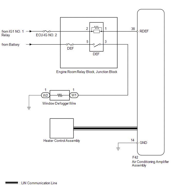
When the back door power window is fully closed and the rear window defogger switch is turned on, a rear window defogger activation request signal is sent via the LIN communication line to the air conditioning amplifier.
WIRING DIAGRAM
CAUTION / NOTICE / HINT
NOTICE:
- Inspect the fuses for circuits related to this system before performing the following inspection procedure.
- Since the window defogger system has functions that use LIN communication, first confirm that there is no malfunction in the communication system by inspecting the LIN communication functions in accordance with the "How to Proceed with Troubleshooting" procedures. Then, conduct the following inspection procedure.
- Since the window defogger system does not operate if the back power window is not operating normally, confirm that the back power window of the power window system is operating normally before performing troubleshooting.
PROCEDURE
|
1. |
PERFORM ACTIVE TEST USING TECHSTREAM (DEFOGGER RELAY [REAR]) |
(a) Using the Techstream, perform the Active Test (See page
.gif) ).
).
Air Conditioner
|
Tester Display |
Test Part |
Control Range |
Diagnostic Note |
|---|---|---|---|
|
Defogger Relay (Rear) |
DEF relay operation |
OFF/ON |
- |
OK:
The DEF relay operates normally.
| NG | .gif) |
GO TO STEP 3 |
|
.gif)
|
2. |
REPLACE HEATER CONTROL ASSEMBLY |
(a) Temporarily replace the heater control with a new or normally functioning
one (See page ).
(b) Check the rear defogger function.
OK:
The window defogger function operates normally.
| OK | |
END (HEATER CONTROL ASSEMBLY IS DEFECTIVE) |
| NG | |
REPLACE AIR CONDITIONING AMPLIFIER ASSEMBLY |
|
3. |
INSPECT DEF RELAY |
|
(a) Remove the DEF relay from the engine room relay block, junction block. |
|
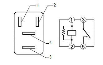
(b) Measure the resistance according to the value(s) in the table below.
Standard Resistance:
|
Tester Connection |
Condition |
Specified Condition |
|---|---|---|
|
3 - 5 |
Battery voltage applied between terminals 1 and 2 |
Below 1 Ω |
|
3 - 5 |
Battery voltage not applied between terminals 1 and 2 |
10 kΩ or higher |
| NG | |
REPLACE DEF RELAY |
|
|
4. |
CHECK HARNESS AND CONNECTOR (BATTERY - DEF RELAY) |
|
(a) Remove the DEF relay from the engine room relay block, junction block. |
|
(b) Measure the voltage according to the value(s) in the table below.
Standard Voltage:
|
Tester Connection |
Switch Condition |
Specified Condition |
|---|---|---|
|
DEF relay terminal 2 - Body ground |
Ignition switch off |
Below 1 V |
|
DEF relay terminal 2 - Body ground |
Ignition switch ON |
11 to 14 V |
|
DEF relay terminal 5 - Body ground |
Always |
11 to 14 V |
|
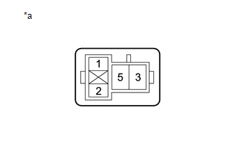
*a |
Front view of wire harness connector (to DEF Relay) |
| NG | |
REPAIR OR REPLACE HARNESS OR CONNECTOR |
|
|
5. |
CHECK HARNESS AND CONNECTOR (AIR CONDITIONING AMPLIFIER ASSEMBLY - DEF RELAY AND BODY GROUND) |
(a) Disconnect the F42 air conditioning amplifier connector.
(b) Remove the DEF relay from the engine room relay block, junction block.
(c) Measure the resistance according to the value(s) in the table below.
Standard Resistance:
|
Tester Connection |
Condition |
Specified Condition |
|---|---|---|
|
DEF relay terminal 1 - F42-38 (RDEF) |
Always |
Below 1 Ω |
|
F42-14 (GND) - Body ground |
Always |
Below 1 Ω |
|
F42-38 (RDEF) - Body ground |
Always |
10 kΩ or higher |
| NG | |
REPAIR OR REPLACE HARNESS OR CONNECTOR |
|
|
6. |
INSPECT AIR CONDITIONING AMPLIFIER ASSEMBLY |
(a) Reconnect the F42 air conditioning amplifier connector.
|
(b) Measure the voltage according to the value(s) in the table below. Standard Voltage:
|
|

| NG | |
REPLACE AIR CONDITIONING AMPLIFIER ASSEMBLY |
|
|
7. |
CHECK HARNESS AND CONNECTOR (BACK DOOR GLASS - DEF RELAY AND BODY GROUND) |
(a) Disconnect the W1 and W2 back door glass (window defogger wire) connectors.
(b) Remove the DEF relay from the engine room relay block, junction block.
(c) Measure the resistance according to the value(s) in the table below.
Standard Resistance:
|
Tester Connection |
Condition |
Specified Condition |
|---|---|---|
|
DEF relay terminal 3 - W1-1 |
Always |
Below 1 Ω |
|
W2-1 - Body ground |
Always |
Below 1 Ω |
|
W1-1 - Body ground |
Always |
10 kΩ or higher |
| OK | |
REPLACE BACK DOOR GLASS (WINDOW DEFOGGER WIRE) |
| NG | |
REPAIR OR REPLACE HARNESS OR CONNECTOR |
 Data List / Active Test
DATA LIST / ACTIVE TEST
1. ACTIVE TEST
HINT:
Using the Techstream to perform Active Tests allows relays, VSVs, actuators and
other items to be operated without removing any parts. This non-intrus ...
 Window Defogger Wire
On-vehicle Inspection
ON-VEHICLE INSPECTION
PROCEDURE
1. INSPECT BACK WINDOW GLASS (DEFOGGER WIRE)
NOTICE:
When cleaning the glass, wipe the glass along the wire using a soft,
dry c ...
Other materials about Toyota 4Runner:
Front seats
Manual seat
1. Seat position adjustment lever
2. Vertical height adjustment lever (driver’s side only)
3. Seatback angle adjustment lever
4. Lumber support adjustment switch (driver’s side only)
Power seat
1. Seat position adjustment switch
...
Door Side Airbag Sensor RH Malfunction (B1690/15,B1695/16)
DESCRIPTION
The side airbag sensor LH or RH consists of the safing sensor, diagnostic circuit,
lateral deceleration sensor, etc.
If the center airbag sensor receives signals from the lateral deceleration sensor,
it determines whether the SRS should be ac ...

0.0274