Toyota 4Runner: Window Defogger Wire
On-vehicle Inspection
ON-VEHICLE INSPECTION
PROCEDURE
1. INSPECT BACK WINDOW GLASS (DEFOGGER WIRE)
NOTICE:
- When cleaning the glass, wipe the glass along the wire using a soft, dry cloth. Take care not to damage the defogger wires.
- Do not use detergents or glass cleaners that have abrasive ingredients.
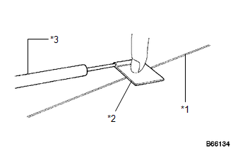
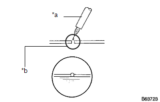
- When measuring voltage, wrap a piece of tin foil around the tip of the negative (-) tester probe and press the foil against the wire with your finger as shown in the illustration.
 Text in Illustration
|
*1 |
Defogger Wire |
|
*2 |
Tin Foil |
|
*3 |
Tester Probe |
(a) Turn the ignition switch to ON.
(b) Turn the defogger switch on.
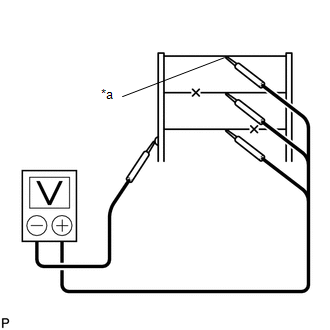
(c) Measure the voltage at the center of each defogger wire as shown in the illustration.
Standard Voltage:
|
Voltage |
Criteria |
|---|---|
|
Approx. 5 V |
Wire is not broken |
|
Approx. 10 or 0 V |
Wire is broken |
|
*a |
Center |
HINT:
If there is approximately 10 V, the wire may be faulty between the center of the wire and the wire end on the battery side. If there is no voltage, the wire may be faulty between the center of the wire end and the wire end on the ground side.
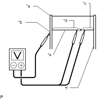
(d) Place the voltmeter positive (+) lead against the defogger wire on the battery side.
(e) Place the voltmeter negative (-) lead with the foil strip against the wire on the ground side.
(f) Slide the positive (+) lead from the battery side to the ground side.
(g) The point where the voltage drops from approximately 10 V to 0 V is where the defogger wire is broken.
HINT:
If the defogger wire is not broken, the voltmeter indicates 0 V at the positive (+) end of the defogger wire and gradually increases to approximately 12 V as the meter probe moves to the other end.
Text in Illustration|
*a |
Ground Side |
|
*b |
Foil Strip |
|
*c |
Approximately 10 V |
|
*d |
0 V |
|
*e |
Broken Wire |
|
*f |
Battery Side |
Repair
REPAIR
PROCEDURE
1. REPAIR DEFOGGER WIRE
(a) Clean the broken wire tips with grease, wax and silicone remover.
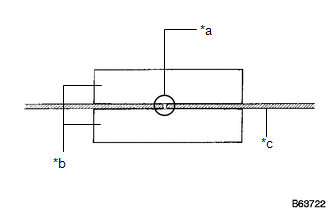
(b) Place masking tape along both sides of the wire.
(c) Thoroughly mix the repair agent.
DuPont paste:
No. 4817 or equivalent
Text in Illustration|
*a |
Repair Point |
|
*b |
Masking Tape |
|
*c |
Broken Wire |
|
(d) Using a fine tip brush, apply a small amount of the agent to the wire. Text in Illustration
|
|
(e) After a few minutes, remove the masking tape.
NOTICE:
Do not allow electricity to flow in the defogger wire for at least 24 hours.
 Rear Window Defogger System does not Operate
DESCRIPTION
When the back door power window is fully closed and the rear window defogger
switch is turned on, a rear window defogger activation request signal is sent via
the LIN communication li ...

Other materials about Toyota 4Runner:
Vehicle Speed Signal Error (Test Mode DTC) (C2191/91)
DESCRIPTION
The tire pressure warning ECU receives a vehicle speed signal from the combination
meter. This DTC is stored upon entering test mode and cleared when a vehicle speed
signal of 20 km/h (12 mph) is detected for 3 seconds or more. This DTC is sto ...
Front Passenger Side Solar Sensor Short Circuit (B14A3)
DESCRIPTION
The automatic light control sensor (solar sensor), which is installed on the
upper side of the instrument panel, detects sunlight and controls the air conditioning
in auto mode. The output current from the solar sensor varies according to th ...

0.0071