Toyota 4Runner: Reassembly
REASSEMBLY
PROCEDURE
1. INSTALL BACK DOOR UPPER DAMPER STAY BRACKET LH
.gif)
2. INSTALL BACK DOOR UPPER DAMPER STAY BRACKET RH
HINT:
Use the same procedure as for the LH side.
3. INSTALL BACK DOOR STAY BOLT (for LH Side)
4. INSTALL BACK DOOR STAY BOLT (for RH Side)
HINT:
Use the same procedure as for the LH side.
5. INSTALL BACK DOOR DAMPER STAY SUB-ASSEMBLY LH
6. INSTALL BACK DOOR DAMPER STAY SUB-ASSEMBLY RH
HINT:
Use the same procedure as for the LH side.
7. INSTALL BACK DOOR PANEL CUSHION
|
(a) Attach the claw to install the 2 back door panel cushions. |
|
.png)
8. INSTALL BACK DOOR LOWER STOPPER
|
(a) Attach the guide to install the back door lower stopper with the bolt. Torque: 8.0 N·m {82 kgf·cm, 71 in·lbf} HINT: Use the same procedure as for the LH side. |
|
.png)
9. INSTALL BACK DOOR CONTROL SWITCH (w/ Smart Key System)
|
(a) Attach the claw to install the back door control switch. |
|
.png)
(b) Install the screw.
10. INSTALL LICENSE PLATE LIGHT ASSEMBLY
11. INSTALL BACK DOOR OPENER SWITCH ASSEMBLY
|
(a) Install the back door opener switch assembly with the 2 screws. |
|
.png)
(b) Attach the guide.
(c) Connect the connector.
12. INSTALL REAR TELEVISION CAMERA ASSEMBLY
13. INSTALL BACK DOOR OUTSIDE GARNISH
14. INSTALL BACK DOOR LOCK CYLINDER (w/o Smart Key System)
|
(a) Install the back door lock cylinder with the 2 nuts. Torque: 5.5 N·m {56 kgf·cm, 49 in·lbf} |
|
.png)
(b) Connect the connector.
15. INSTALL POWER WINDOW REGULATOR MOTOR ASSEMBLY LH
16. INSTALL BACK DOOR POWER WINDOW REGULATOR SUB-ASSEMBLY
(a) Apply MP grease to the sliding and rotating parts of the back door power window regulator sub-assembly.
|
(b) Install the back door power window regulator sub-assembly with the 5 bolts. Torque: 8.0 N·m {82 kgf·cm, 71 in·lbf} NOTICE: Do not drop the back door power window regulator sub-assembly as it may be damaged. |
|
.png)
|
(c) Connect the power window regulator motor assembly LH connector. |
|
.png)
17. INSTALL BACK DOOR LOCK ASSEMBLY
18. INSTALL OUTER BACK DOOR GLASS WEATHERSTRIP ASSEMBLY
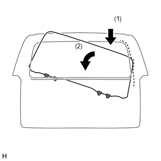
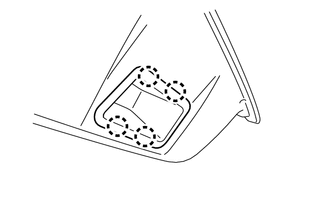
19. INSTALL BACK DOOR GLASS
(a) Temporarily connect the multiplex network body ECU connectors.
(b) Connect the cable to the negative (-) battery terminal.
(c) Move the back door glass until the bracket can be seen through the service holes.
(d) Disconnect the cable from the negative (-) battery terminal.
NOTICE:
When disconnecting the cable, some systems need to be initialized after the cable
is reconnected (See page ).
(e) Disconnect the multiplex network body ECU connectors.
|
(f) Insert the back door glass as shown in the illustration. NOTICE: Do not damage the back door glass and back door panel. |
|
|
(g) Install the back door glass with the 4 bolts. Torque: 8.0 N·m {82 kgf·cm, 71 in·lbf} |
|
.png)
(h) Connect the 2 defogger connectors and install the bolt.
.png)
Torque:
8.0 N·m {82 kgf·cm, 71 in·lbf}
NOTICE:
If the SUS plate is bent, broken, etc., replace the wire harness.
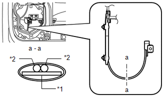 Text in Illustration
|
*1 |
SUS Plate |
|
*2 |
Wire Harness |
|
(i) Install the hole plug. |
|
.png)
20. INSTALL BACK DOOR GLASS RUN
|
(a) Install the back door glass run. |
|
.png)
21. INSTALL REAR WIPER STOPPER
|
(a) Attach the claw and guide to install the rear wiper stopper. |
|
22. INSTALL REAR WASHER NOZZLE
23. INSTALL NO. 1 BACK WINDOW WIPER MOTOR BRACKET
|
(a) Attach the 2 clips to install the No. 1 back window wiper motor bracket. |
|
.png)
(b) Install the 3 bolts.
Torque:
8.0 N·m {82 kgf·cm, 71 in·lbf}
24. INSTALL REAR WIPER MOTOR AND BRACKET ASSEMBLY
25. INSTALL REAR WIPER ARM
26. INSTALL REAR SPOILER SUB-ASSEMBLY
27. INSTALL REAR NO. 1 SPOILER COVER
28. INSTALL BACK DOOR OUTSIDE MOULDING LH
29. INSTALL BACK DOOR OUTSIDE MOULDING RH
30. INSTALL BACK DOOR SERVICE HOLE COVER LH
|
(a) Attach the 2 clips to install the back door service hole cover LH. |
|
.png)
(b) Install the 5 screws.
(c) Attach the clamp to install the wire harness.
31. INSTALL BACK DOOR SERVICE HOLE COVER RH
|
(a) Attach the 2 clips to install the back door service hole cover RH. |
|
.png)
(b) Install the 5 screws.
(c) Attach the clamp to install the wire harness.
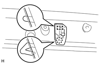
32. INSTALL NO. 2 BACK DOOR SERVICE HOLE COVER
(a) Apply butyl tape to the back door panel.
|
(b) Install a new No. 2 back door service hole cover. Text in Illustration
|
|
(c) Attach the No. 2 back door service hole cover according to the reference points on the back door panel.
NOTICE:
Securely install the No. 2 back door service hole cover preventing wrinkles and air bubbles.
33. INSTALL MULTIPLEX NETWORK DOOR ECU
|
(a) Attach the 2 clips to install the multiplex network door ECU to the door panel. |
|
.png)
|
(b) Install the 3 screws. |
|
.png)
|
(c) Connect the 3 connectors and attach the 2 clamps. |
|
.png)
34. INSTALL REAR NO. 2 SPEAKER ASSEMBLY
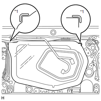
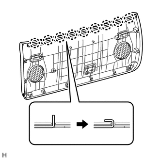
35. INSTALL BACK DOOR GLASS WEATHERSTRIP
|
(a) Install the back door glass weatherstrip on the back door trim panel assembly and fold down the 9 claws as shown in the illustration. |
|
36. INSTALL BACK DOOR TRIM PANEL ASSEMBLY
|
(a) Attach the 12 clips to install the back door trim panel assembly. |
|
.png)
37. INSTALL ASSIST STRAP ASSEMBLY
|
(a) Install the assist strap assembly with the bolt. |
|
.png)
38. INSTALL ASSIST STRAP HOLE COVER
|
(a) Attach the guide and 2 claws to install the assist strap hole cover. |
|
.png)
39. INSTALL BACK DOOR LOCK PROTECTOR SUB-ASSEMBLY
|
(a) Attach the 2 claws to install the back door lock protector sub-assembly. |
|
.png)
40. INSTALL DOOR PULL HANDLE
|
(a) Attach the 4 claws to install the door pull handle. HINT: Use the same procedure for all door pull handles. |
|
 Adjustment
ADJUSTMENT
CAUTION / NOTICE / HINT
HINT:
Use the same procedure for the RH side and LH side.
The following procedure is for the LH side.
Centering bolts are used to mount the do ...
 Back Door Opener Switch
Components
COMPONENTS
ILLUSTRATION
Disassembly
DISASSEMBLY
PROCEDURE
1. REMOVE ASSIST STRAP HOLE COVER
2. REMOVE ASSIST STRAP ASSEMBLY
3. REMOVE BACK DOOR TRIM PANEL ASSEMBLY
4 ...
Other materials about Toyota 4Runner:
Communication Malfunction (Bus Ic) (B1497)
DESCRIPTION
The air conditioning harness assembly connects the No. 1 air conditioning amplifier
assembly and each servo motor. The No. 1 air conditioning amplifier assembly supplies
power and sends operation instructions to each servo motor through the No ...
Calibration
CALIBRATION
1. DESCRIPTION
(a) After replacing VSC-related components, clearing and reading the sensor calibration
data is necessary.
(b) Follow the chart to perform calibration.
Part Replaced
Necessary Operation
Ma ...

0.0203