Toyota 4Runner: Adjustment
ADJUSTMENT
CAUTION / NOTICE / HINT
HINT:
- Use the same procedure for the RH side and LH side.
- The following procedure is for the LH side.
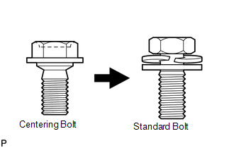
- Centering bolts are used to mount the door hinge to the vehicle body and door. The door cannot be adjusted with the centering bolts installed. Substitute the centering bolts with standard bolts and washers when making adjustments.
- The specified torque for standard bolts is shown in the standard bolt
chart (See page
.gif) ).
).
PROCEDURE
1. INSPECT BACK DOOR
(a) Check that the clearance measurements of areas A through G are within each standard range.
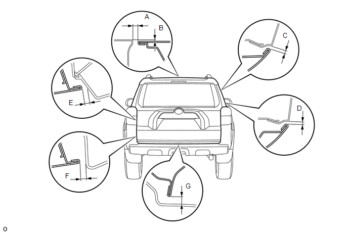
Standard:
|
Area |
Measurement |
Area |
Measurement |
|---|---|---|---|
|
A |
9.5 to 12.5 mm (0.374 to 0.492 in.) |
B |
0.0 to 3.0 mm (0.0 to 0.118 in.) |
|
C |
4.0 to 7.0 mm (0.157 to 0.276 in.) |
D |
4.2 to 7.2 mm (0.165 to 0.283 in.) |
|
E |
6.4 to 9.4 mm (0.252 to 0.370 in.) |
F |
6.7 to 9.7 mm (0.264 to 0.382 in.) |
|
G |
8.6 to 11.6 mm (0.339 to 0.457 in.) |
- |
- |
2. ADJUST BACK DOOR
|
(a) Before adjusting the upper end of the back door up and down or left and right, loosen the bolts. |
|
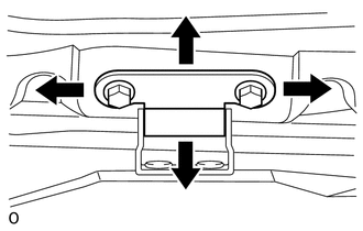
(b) Tighten the body side hinge after the adjustment.
Torque:
20 N·m {199 kgf·cm, 15 ft·lbf}
|
(c) Using a T40 "TORX" socket wrench, slightly loosen the striker mounting screws. |
|
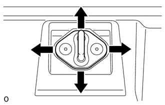
(d) Using a brass bar and hammer, hit the striker to adjust its position.
(e) Using a T40 "TORX" socket wrench, tighten the striker mounting screws after the adjustment.
Torque:
27 N·m {275 kgf·cm, 20 ft·lbf}
 Disassembly
DISASSEMBLY
PROCEDURE
1. DISCONNECT CABLE FROM NEGATIVE BATTERY TERMINAL
NOTICE:
When disconnecting the cable, some systems need to be initialized after the cable
is reconnected (See page ).
2 ...
 Reassembly
REASSEMBLY
PROCEDURE
1. INSTALL BACK DOOR UPPER DAMPER STAY BRACKET LH
2. INSTALL BACK DOOR UPPER DAMPER STAY BRACKET RH
HINT:
Use the same procedure as for the LH side.
3. INSTALL BACK DOOR ...
Other materials about Toyota 4Runner:
Installation
INSTALLATION
PROCEDURE
1. INSTALL LOWER NO. 2 INSTRUMENT PANEL AIRBAG ASSEMBLY
(a) Connect the connector.
NOTICE:
When handling the airbag connector, take care not to damage the airbag
wire harness.
...
Adjustment
ADJUSTMENT
CAUTION / NOTICE / HINT
HINT:
Use the same procedure for the RH side and LH side.
The following procedure is for the LH side.
Centering bolts are used to mount the door hinge to the vehicle body
and door. The door cannot b ...

0.0138